Acetylene Welding
Description
This section is from the book "Welding And Cutting Metals By Aid Of Gases Or Electricity", by L. A. Groth. Also available from Amazon: Welding and cutting metals by aid of gases or electricity.
Acetylene Welding
In the case of automatic or non-automatic welding plants the gas from the generator A passes into a condenser to cool it and to remove any tarry products ; it enters thereafter a washing apparatus B, filled with water, to extract water-soluble impurities; from thence it travels to the gasometer C. In leaving the gasometer the acetylene passes to the purifier D, and travels from there through ordinary mains E to a back-pressure hydraulic valve F. It is then ready to be drawn from these into the blowpipe G.
The oxygen, compressed into the cylinder H, passes into the pressure regulator J; a rubber tube K leads it from there into the blowpipe G, where it is mixed with the acetylene before the two gases leave the nozzle, in order to effect the welding of the plates L.
If the generator is of the carbide-to-water type, the condenser may be omitted, and the washer is required to retain any lime-froth.
Any number of blowpipes can be worked from these mains M, but at each point where gas will be used for a blowpipe a back-pressure hydraulic valve must be fixed.
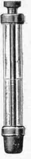
Regulators. Hydraulic Pressure-Regulating Valve.
The back-pressure hydraulic valve precludes the possibility of oxygen at any time flowing into the gasholder and also air from being drawn into the acetylene mains. Its action, illustrated by Fig. 7, is as follows: -
The acetylene pipe from the gas-holder is connected to the branch /, and the acetylene pipe leading to the blowpipe is connected to the branch d. Water is poured into the open chamber b until it reaches the closed vessel a.
The valve is then in working order. The filling pipe c is made long enough to hold a column of water equal to the pressure of the acetylene holder, which should be about 9 in. of water. The supply of acetylene to the blowpipe may be regulated by the tap on the branch d (where taps do not exist on the blowpipe itself), and the tap at f may be left permanently open.
Should the blowpipe nozzle at any time become choked whilst the oxygen supply remained unchecked this gas would be forced by its superior pressure along the acetylene pipe. The back pressure thus caused acting on the surface of the water in the chamber a would force this water up the pipe e, and prevent the oxygen from entering the acetylene supply pipe beyond the tap of the hydraulic valve.
Fig. 7. - Draeger's Patent.
High-Pressure Automatic Regulator (Fig. 8). - This is an automatic regulator which is made to deliver gas at any required pressure up to about 30 lbs. per square inch. The pressure can be adjusted by unscrewing the screw R for low pressure, or by screwing down R for high pressure. The indicator M indicates the pressure of delivery as set by E. The maximum pressure at which the regulator will work is marked by a red line on the indicator M, and if this pressure is exceeded (by screwing R too far) a safety valve S will open and release the excess pressure. The tap H lor controlling the supply is a convenience which the safety valve S renders possible. N is the delivery nozzle, and F is a gauge for registering pressure of gas in cylinder. This regulator is extensively used in blowpipe work.
High-Pressure Automatic Regulator (Fig. 9) {Patent). - This regulator, fitted with or without high-pressure gauge, possesses exactly the same features as the one in the preceding illustration. It is suitable for every class of work. It is of substantial construction, and has been specially designed for workshop use. It is specially recommended for all kinds of blowpipe work. The adjustable screwed socket on the side of the regulator is graduated in pounds per square inch, and the regulator can be set by this means to any desired constant pressure, thus enabling the usual low-pressure gauge to be dispensed with.
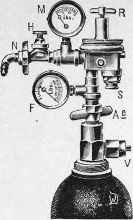
Fig. 8.
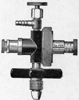
Fig. 9.
Gas Pressure Gauge (Fig. 10). - These pressure gauges are useful to frequent users of oxygen cylinders, and particularly to agents, as a means of ascertaining the quantity of gas in cylinders.
The gauges as illustrated are specially marked in atmospheres and feet, and the cubic contents of any cylinder may be readily calculated in the following manner: -
The figures on outer ring indicate pressure in atmospheres; 120 atmospheres being the pressure to which all cylinders are charged. The figures on inner ring indicate the number of cubic feet of gas contained in a 10-foot cylinder. To calculate the quantity of gas contained in any cylinder, multiply the figure to which the needle points by the multiple of 10 ; thus, if the gauge is attached to a 40-foot cylinder, and the needle points to 6, then 6 X 4 = 24 feet = quantity of gas in cylinder.
Both types of pressure gauge are fitted with safety checks in the stem to prevent a sudden rush of gas into the gauge tube when the cylinder valve is opened. Leak Tester (Fig. 11). - To use the tester. Press the conical rubber end into the outlet of the cylinder valve. If there is the slightest leakage of gas it will be at once indicated by bubbles passing through the water. If, on the other hand, there is no leakage, bubbles will not be perceptible.
The instrument is a handy substitute for the clumsy method of testing for leakage by pouring some water into the socket of the valve. It is only about 4 inches long, and can be carried in the waistcoat pocket. The water is found to evaporate very slowly, and will only require renewal at long intervals of time. N.B. - Oil must not be used in the tester.
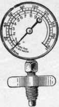
Fig. 10.
Continue to:
My Books

