Acetylene Welding. Continued
Description
This section is from the book "Welding And Cutting Metals By Aid Of Gases Or Electricity", by L. A. Groth. Also available from Amazon: Welding and cutting metals by aid of gases or electricity.
Acetylene Welding. Continued
Fig. 11.
Steel Cylinders (Fig. 12). - All cylinders sold or employed by the British Oxygen Company are guaranteed to be made of steel complying with the British Government recommendations. They are made to the company's own specifications, and are regularly inspected during manufacture by one of the company's engineers. They are all re-annealed, valved, and tested hydrauli-cally to a pressure of 1 1/2 tons per square inch, in the company's works, before being filled with gas. The company's methods of annealing, testing and filling cylinders are in accordance with the British Government recommendations.
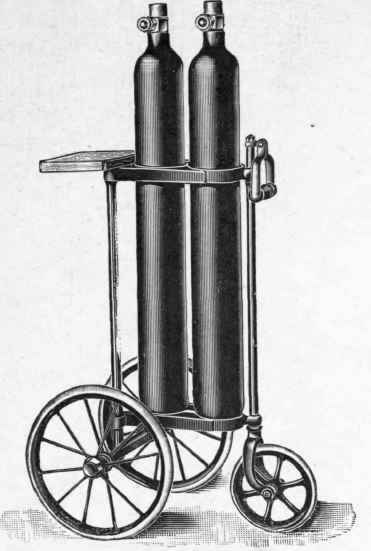
Fig. 12. - Trolley Stand for Pair of Cylinders.
*Cubic contents in feet fully charged. | Approximate external diameter in inches. | Approximate length over all in inches including valve. | Approximate weight in lbs. (empty). |
10 | 4 | 19 | 13 |
20 | 4 | 35 | 23 |
40 | 5 1/2 | 36 | 43 |
60 | 7 | 32 | 66 |
80 | 7 | 41 | 85 |
100 | 7 | 49 | 103 |
* All oxygen cylinders are filled to 120 atmospheres pressure.
Annealing. - In accordance with Government recommendations, all cylinders (before being subjected to the usual hydraulic test for the first time) must be annealed. All cylinders received at the company's works to be filled for the first time will, after annealing, be tested hydraulically to a pressure of 1 1/2 tons per square inch, and afterwards registered. The company re-test all cylinders annually, a periodical re-test being necessary as much in the interest of the customer as of the company.
All hydraulic testing of cylinders is done by the company in their stretch testing apparatus (Fig. 13). This system was first introduced by the British Oxygen Company twenty years ago. It was officially approved by the British Government's Cylinder Committee of 1896, and has recently been added to the official Cylinder Regulations of Germany and other countries. Being an apparatus of general interest it is now illustrated and described below : -
This apparatus consists of a cast-iron chamber B, in which the cylinder A to be tested is suspended. D, an hydraulic pump employed for testing the cylinder A. E, a gauge glass communicating with the bottom of chamber B; and C, an indiarubber joint ring, which is capable of closing and making a perfect joint round the shoulder of the cylinder. The method of testing is as follows: - Both cylinder A and chamber B are filled with water to the exclusion of all air, and a perfect joint is made round the neck of the cylinder by inflating the indiarubber ring C, which can be instantaneously done by water pressure from the ordinary main supply. When the cylinder is gradually subjected to the test pressure by means of the pump D, its expansion is measured by the displacement of water from the chamber B, and this displacement is indicated by the rise of the water level in the gauge glass, which continues until the maximum test pressure is obtained. The pressure is then released, and if no permanent stretch has been given to the metal, the water will return to its original level in the indicator. If, however, any permanent stretch has been caused this will not be the case, and the cylinder would therefore be rejected as unfit for use.
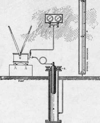
Fig. 13. - Stretch Testing Apparatus for Cylinders.
The value of this apparatus is obvious. Its employment insures that a cylinder is never strained beyond the "elastic limit" of its metal, and without this safeguard no hydraulic test is reliable.
In blowpipe work the only object of a combined regulator and high-pressure gauge is to guard against the oxygen supply running short in the middle of a job. Pressure gauges permanently attached to regulators are a fruitful source of trouble. They soon become inaccurate (particularly the small type so frequently employed) and being delicate in construction they are liable to injury in workshop handling. The connector (Fig. 14) is an excellent substitute for the pressure gauge permanently attached to a regulator. The regulator is in communication with two cylinders A and B, one of which can be shut off when the other is in use. Thus, if the valve of cylinder A and the pipe valve a are open whilst the valve of cylinder B and the pipe valve b are closed, oxygen flows from cylinder A through the regulator until it begins to empty. The valves of cylinder A are then closed and those of cylinder B opened. Oxygen will then flow from cylinder B whilst the empty A cylinder can be removed and replaced by a full one. Thus it will be readily seen that a continuous supply of oxygen can be maintained to the blowpipes by the employment of this connector, and for permanent work regulators with this connector will be found more convenient and reliable than those fitted with pressure gauges. A separate pressure gauge (Fig. 10, p. 44) - preferably of the larger diameter - should be in the possession of all constant users of cylinders to enable them to check the contents of cylinders when they arrive from the compressing factory.
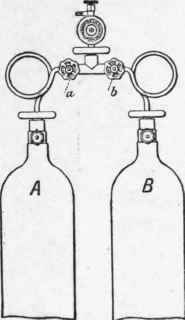
Fig. 14. - Connector between Regulator and two Cylinders.
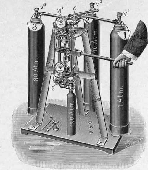
Fig. 15. - Draeger's High-Pressure Refill Pump.
Draeger's High-Pressure Refilling Pump, as illustrated in Fig. 15, enables trade cylinders to be filled, in various stages, from storage vessels containing the gas under different high pressures.
The three storage vessels, 1, 2, 3, containing the gas at pressures of, say, 1, 40, and 80 atmospheres, are connected by means of strong piping to the pump valves at K. The manometer M1 shows the pressure in the respective storage vessels from which the gas is to be supplied, and the manometer M2 the pressure obtained in the trade-cylinder. S represents the closing valve of the pump when the trade-cylinders are being exchanged, and T is the closing valve of the cylinders.
Continue to:
My Books

