


An Easily Made Am-Meter
Description
This section is from the book "Amateur Work Magazine Vol4". Also available from Amazon: Amateur Work.
An Easily Made Am-Meter
Oscar N. Dame
Every amateur should possess an accurate amater for measuring battery current and general laboratory test-ing. While the high grade instruments for sale by apparatus dealers are beyond the means of most students, it is possible to construct an efficient instrument for a small sum. Much of the construction can be done with ordinary household tools, but there are a few portions of the meter which require absolute align-ment, and which will give better satisfaction if fitted by an experienced hand. This instrument is to be used in a vertical position, presumably fastened to the wall near the work bench or test table.
Upon the true workings of the bearings depends the accuracy of the machine. The style of pivot is shown in Fig. 1. With this conical indentation cut smoothly and accurately in the end of a machine screw with a fine jewellers' drill, and a hardened staff constructed of a piece of old clock staff, as in Fig. 2, there should be little friction. If, however, the reader should desire jewelled accuracy, I would advise him to construct all of the instrument except the pivot portion, and then send his machine screws to a jewel setter, who will insert ordinary jewels for about fifty cents each. While the dollar spent for this professional assistance may add greatly to the accuracy, I believe for ordinary purposes it is just as well to construct without jewels, as I did my first one, and attend to the improvements afterwards, if it does not meet all requirements.
Procure a soft iron ring 4 in. in diameter, of | in. stock. Such a ring is sold at all hardware stores for hitching posts, etc. Procure a piece of brass 5 in. Jong 5/8 wide by 3-16 thick. Measure one half inch from one end and center for a 3/8 in. hole, to be drilled there. Center also 4 in. below and drill a second 3/8 hole. It will be seen that these holes apply to a 4 in., 3/8 ring. If the amateur is unable to procure a 4 in., 3/8 ring, the measurement given for holes will have to be altered to conform. Next, by two cuts of the hack saw cut out about 1 in. of the ring. This will permit slipping the rings into the holes in the brass rod. Solder is then carefully applied to hold the ring in place. Find half the distance between the inside edges of the ring and mark same on the brass rod. Here a 1/8 hole is to be drilled where the staff is to be placed and fixed with solder.
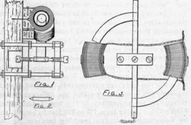
Procure a piece of clock steel, 1/8 stock and 1 in. long, and fashion as in Fig. 2. The ends should be hardened and polished. When this steel is soldered into the shaft there will be about 1/8 of an inch of each end visible. For bearings use two 8-32 machine screws 1/2 in. long. In the end of each drill smoothly to receive the end of the staff. For supports of this bearing take two strips of brass 1/4X1/2X1 1/2. Holes are drilled near the ends and in the center of these pieces and, with machine screws and nuts to fit, a support exactly like the figure is constructed. If the screws are quite long they will serve to pass through the base board. Next, with a tape measure mark off four inches of the ring at top and bottom and cut off this portion. See Fig. 1. Place pendulum in bearings and adjust to swing easily.
The two solenoids are formed of paper, fiber or hard rubber and should be fully 5/8 inside diameter and 1 1/4 long, smooth inside and bent to conform with the shape of the metal ring pieces which enter them. Each tube should be wound with four layers of No. 20 magnet wire. The tubes are then fastened to the baseboard, as in Fig. 3, by means of metal clips. Fig. 3 also shows the circuit connections. A small 1-16 in; hole is drilled in the lower end of the pendulum and a fine long steel needle inserted for a pointer. To grade this instrument accurately will require some experimenting. A step by step comparison with a standard instrument would be the best way, but with batteries of known voltage and amperage the instrument may be calibrated to meet all ordinary requirements by the insertion of variable resistances in one of the battery wires (thus increasing the resistance of this circuit)
Calculate by one of the formulas of ohms law:E/R = C
For instance: A new dry cell, as tested at the electrical stores, might show 1.4 volts and 7 amperes on short circuit.
Thus: 1.4 / 7 = 2/10 ohms internal resistance.
Any resistance inserted in the external curcuit will cut down the current. And from any standard wire table showing resistance of different gauges of wire per inch, one can prepare sufficient resistances to cut down the current to any desired degree. For example: - The resistance of our two coils is a very small part of an ohm and need not be reckoned with. With 1.4 volts and 2-10 ohms we have 7 amperes. By inserting 1 2-10 ohms additional resistance we have:
1.4/ 1.2 + .2 = 1.4/1.4 = 1 ampere.
Continue to:


My Books

