


Notes On Wireless Teegraphy. IV. Course of the Transmitted Wave and Frequency
Description
This section is from the book "Amateur Work Magazine Vol4". Also available from Amazon: Amateur Work.
Notes On Wireless Teegraphy. IV. Course of the Transmitted Wave and Frequency
L. T. KNIGHT
During the early experiments with telephone transmissions in the original installation between Boston and Providence, a distance of about 50 miles, an enormous battery supply was held in readiness for the first conversation, and it is said to the great surprise of all present in the room where the tests were made, the amount of voltage was cut down from 50 to that of two primary cells, and no harm to transmission resulted.
In the early Atlantic cable tests heavy battery soon gave way to weak battery because experts found the feebler currents more reliable. Now in the present era, with wireless telegraphy foremost in the mind of every transmission specialist, we find the different systems struggling for supremacy by the use of enormously high poles, ranging from 175 to 210 feet in height, and by transformed voltages reaching into six figures. Scores of systems have been patented at the patent offices of this and foreign countries, and in nearly every instance the systems have called for aerials stretching as far into the heavens as the skill of man will permit, following the theory that the effective part of the wire is at the upper end. And where single wires are used it is considered necessary to fit a huge wire capacity cage at the upper end, and the length of this aerial wire from instrument to peak is a factor in determining the wave length.
Presuming that the transmitted wave leaves the aerial at the peak, its course to the other station was construed to be in a straight line, and the expounding of this theory has filled chapter after chapter, and one of the recent books on the subject, in a full page illustration, scales out the course of Marconi's wonderful messages from Canada to Great Britain with dotted precision, explaining the curvature of the earth and the drop of many miles below the ocean's surface which the waves must have taken because of this curvature.
Those who have experimented exhaustively in this matter, find that a transmitted wave leaves the aerial wire perhaps at the peak, and perhaps a short distance from the peak, and its course to the receiving aerial is determined by atmospheric conditions and not by any B line from the top of a 180 foot pole to a 120 foot pole situated on a hill top. It is, therefore, worth propheeying that the high poles will Boon be a thing of the past and waves will be energized by moderately high voltage and extraordinary frequencies. And at the receiving end the coherer and wave detector of the present will be superseded by devices tuned to receive frequencies and not wave volume or wave length.
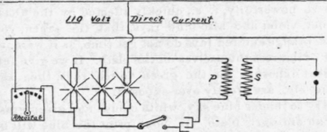
One of the best systems of generating alternating currents of high frequency is here illustrated. Its design is simple, and any amateur possessing a few elec tric light carbons and a condenser of the Leyden jar type, may produce frequencies beyond 10,000 per second. The ordinary 110 volt current is tapped as shown in the illustration. The choke coil has a variable resistance. The capacity of the condenser should be 10 M. F.
To increase the secondary frequency still further, one may construct a frequency coil out of two battery or other smooth jars, one being 4 in. in diameter and about 6 or 7 in. high, and the other 8 in. in diameter and the same height. The smaller jar is wound with one layer of No. 36 bare or covered magnet wire from an inch at the bottom to the top, and each turn must be separated from the adjoining turn fully 1-16 of an inch. A hole is made in the bottom of the jar, and the lower end of the wire is brought up through to the top where it pairs with the other end. On the larger jar is wound in turns 1/3 in. apart, one layer of flat, thin strip metal, preferably of good conductivity. These strips may be } in. wide. This strip circuit is the primary side of the frequency coil, and is connected to the secondary balls of the induction coil. The inner jar is thoroughly insulated from possible moisture by filling the larger jar with insulating oil.
Such a frequency coil may be constructed on a skeleton framework of glass rods, instead of the glass jars, and insulated in any size of jar. Good results can be obtained by using it in connection with a small induction coil operated by dry batteries.
The task of designing an efficient frequency recorder is a puzzling one and will, perhaps, take the form of a device resembling the telephone receiver, worn constantly by the operator, who will receive by ear, or it may take the form of a balance which will become operative when the proper frequency reaches it.
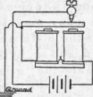
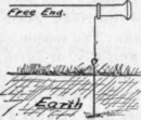
Few amateurs can fail to find amusement and profit in noting the effect of currents of just ordinary frequency sent into the earth from an ordinary doorbell or, what is better, a buzzer. The connections are shown in Fig. 2, and the telephone receiver is used to pick up the tone.
Continue to:


My Books

