Automobile And Cycle Rims. Part 5
Description
This section is from the book "Welding And Cutting Metals By Aid Of Gases Or Electricity", by L. A. Groth. Also available from Amazon: Welding and cutting metals by aid of gases or electricity.
Automobile And Cycle Rims. Part 5
Wrought fittings of all kinds for steam and other pipe installations, such as bends, branch pipes, expansion bends, etc., can be fitted with electrically welded-on flanges, and a few specialities in this direction will be found illustrated below.
Dimensions Of Pipes And Flanges
For steam pressures up to 200 lbs. per square inch, as also the minimum thickness recommended for lap-welded steel pipes for that pressure : -
Bore of Pipe. | External Diam. of Pipe. | Thickness of Pipe. | Diam. of Flange. | Thickness of Flange. | Diam. of Bolt Circle. | Number of Bolts. | Size of Bolts. |
Ins. | Ins. | Ins. | Ins. | Ins. | Ins. | ||
1 | 1 5/16 | 7 W.G. | 4 1/2 | 1 2 | 3 1/4 | 4 | 1 2 |
1 1/2 | 1 7/8 | 6 „ | 5 1/2 | 9 16 | 4 | 4 | 1/2 |
2 | a* | 5 „ | 6 | 8 | 4 5/8 | 6 | 1/2 |
2 1/2 | 3 | 5 „ | 7 | 5/8 | 5 1/2 | 6 | 5/8 |
3 | 3 1/2 | 1/4 in. | 7 1/2 | 3 4 | 6 | 6 | 5/8 |
3 1/2 | 4 | 1/4 " | 8 | 3/4 | 6 1/2 | 6 | 5 8 |
4 | 4 1/2 | 1 | 9 | 7 8 | 7 3/8 | 6 | 3 4" |
5 | 5 1/2 | 1/4 " | 10 | i | 8| | 6 | 3 |
6 | 6 1/2 | 1/4 " | 11 | 1 | 9 3/8 | 8 | 3/4 |
7 | 7 1/2 | 1/4 " | 12 | 1 | 10| | 8 | 3 ¥ |
8 | 8 1/2 | 1/4 " | 13 | 1 | 11 3/8 | 8 | 3 4" |
9 | 9 5/8 | 5/16 " | 15 | 1 1/8 | 13 | 8 | 7 8 |
10 | 10 5/8 | 5/16 " | 17 | 1 1/8 | 14| | 10 | i |
11 | 11 5/8 | 5/16 " | 18 | 1 1/8 | 15 3/4 | 10 | i |
12 | 12 5/8 | 5/16 " | 19 | 1 1/8 | 16f | 12 | 1 |
13 | 13f | 5/16 " | 20 | 1 1/8 | 17| | 12 | 1 |
14 | 14f | 5/16 " | 21 | 1 1/4 | 18 3/4 | 12 | 1 |
15 | 15 3/4 | 3/8 " | 22 | 1 1/4 | 19 3/4 | 16 | 1 |
16 | 16| | 23 | 1 1/4 | 20 3/4 | 16 | 1 | |
17 | 17 3/4 | 3/8 " | 24 | 1 1/4 | 21 3/4 | 16 | 1 |
18 | 18| | 3/8 " | 25 | 1 3/8 | 22 3/4 | 20 | 1 |
19 | 19| | 3/8 " | 26 1/2 | 1 3/8 | 24 | 20 | 1 |
20 | 20 3/4 | 3/8 " | 27 1/2 | 1 3/8 | 25 1/8 | 20 | 1 1/8 |
21 | 2l| | 7/16 " | 29 | 1 3/8 | 26 3/8 | 20 | 1 1/8 |
22 | 22 7/8 | 7/16 " | 30 1/2 | 1 1/2 | 27 5/8 | 20 | 1 1/4 |
23 | 23 7/8 | 7/16 " | 314 | 1 1/2 | 28f | 20 | 1 1/4 |
24 | 24 7/8 | 7/16 " | 32 1/2 | 1 1/2 | 29f | 20 | 1 1/4 |
Figs. 60 to 64 are some illustrations of the firm's electrically welded-on branches, drain pockets and bosses.
These are usually welded on to long lengths of pipe, and consequently the number of flange joints in a range of pipes, which would be necessary if short fittings were used, is materially reduced.

Fig. 60. - Branch and Boss on Centre Line of Pipe.

Fig. 61. - Branch on Centre Line of Pipe.
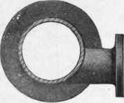
Fig. 62. - Branch off Centre Line of Pipe.

Pig. 63. - Drain Pocket.
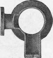
Fig. 64. - Drain Pocket in Section.
Pigs. 60 to 64. - Various Forms of Electrically Welded Branch, etc.
The most general forms of branch are those on centre line of pipe (Fig. 61), and those off centre line of pipe (Fig. 62), but the firm make a speciality of curved branches, which are in favour with some engineers.
Several branches can be welded on to one length of pipe or bend.
Drain pockets (Figs. 63 and 64), with end welded in, and tapped to connect to drain piping, can be welded on to long lengths of steam piping in any position, and are a valuable adjunct to a steam installation, as they dispense with superfluous flange joints, and are considerably stronger and cheaper than any other form of pocket. They are usually welded on to the main pipe directly under the branches to the engines.
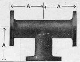
Fig. 65. - Tee.
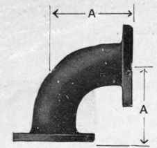
Fig. 66. - Bend.
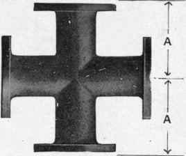
Fig. 67. - Cross.
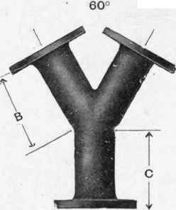
Pig. 68 - " Y" Piece.

Fig. 69. - Breeches Piece.
Figs. 65 to 69. - Wrought Steel Fittings, Electrically Welded.
Bosses for drain piping, steam gauges, thermometers, etc. are welded on pipes, faced, and tapped to requirements.
One distinct advantage peculiar to the electric welding process - as regards wrought fittings - is the ability to meet the long-desired want of the engineer who, having to contend with high pressures, is restricted by a very limited space at his disposal. "With the assistance of the electric welding wrought-steel tees, crosses, "Y" pieces, bends, and breeches pieces - all fitted with welded flanges - can be supplied of shorter dimensions than can be made by any other process.
Figs. 65 to 69 and the following table, giving the minimum dimensions for each size up to 36 ins. diameter of the above fittings, will no doubt be of interest as indicating what may now be supplied for restricted positions.
Minimum Dimensions
Bore. | A | B | c | D |
Ins. | Ins. | Ins. | Ins. | Ins. |
1 | 3 1/2 | 3 3/4 | 2 3/4 | 6 |
2 | 4* | 5 1/4 | 3i | 7* |
2 1/2 | 5 | 6 | 3 1/2 | 8 1/2 |
3 | 5 1/2 | 7 | 4 | 9* |
8} | 6 | 7* | 4 1/4 | 10i |
4 | 6 1/2 | 8* | 4 1/2 | 11 |
5 | 7 | 9 3/4 | 4 3/4 | 12 |
6 | 8 | 11 | 5 | 13 |
7 | 8* | 12 1/2 | 5 1/2 | 14* |
8 | 9 | 13 1/2 | 5 1/2 | 16 |
9 | 10 | 14 3/4 | 5 3/4 | 18 |
10 | 11 | 16 | 6 | 20 |
11 | 11* | 17 1/4 | 6i | 21 |
12 | 12 1/2 | 18J | 6 1/4 | 22 |
13 | 13 | 19 1/4 | 6 1/4 | 23 |
14 | 13 1/2 | 20 1/2 | 6 1/2 | 25 |
15 | 14 | 21f | 6 3/4 | 26 |
16 | 14* | 22} | 6 3/4 | 27 |
17 | 15 | 28 3/4 | 6| | 28 |
Bore. | A | B | c | D |
Ins. | Ins. | Ins. | Ins. | Ins. |
18 | 15* | 25 | 7 | 29 |
19 | 16 1/2 | 26 | 7 | 30* |
20 | 17 | 27 1/2 | 7* | 31* |
21 | 18 | 28| | 7 3/4 | 33 |
22 | 19 | 30 | 8 | 35 |
23 | 19 1/2 | 31 | 8 | 36 |
24 | 20 | 32 | 8 | 37 |
25 | 21 | 33 1/2 | 8 1/2 | 39 |
26 | 22 | 34 1/2 | 8* | 40 |
27 | 23 | 36 | 9 | 41 |
28 | 24 | 37 | 9 | 42 |
29 | 25 | 38 | 9 | 43 |
30 | 26 | 39* | 9 1/2 | 44 |
31 | 27 | 40 1/2 | 9 1/2 | 46 |
32 | 28 | 42 | 10 | 47 |
33 | 29 | 43 | 10 | 48 |
34 | 30 | 44* | 10* | 49 |
35 | 31 | 45* | 10* | 50 |
36 | 32 | 47 | 11 | 51 |
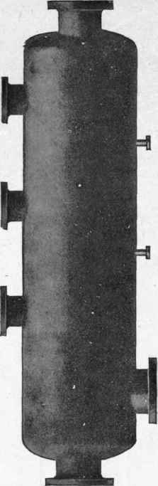
Fig. 70. - Elevation.
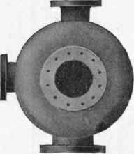
Fig. 71. - End View.
Figs. 70 to 71. - Wrought Steel Steam Receiver.
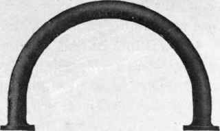
Fig. 72. - Double Bend.
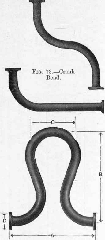
Fig. 74. - "Horseshoe" Type.
Figs. 70 to 74. - Receiver and Bends, Electrically Welded.
Four receivers (Figs. 70, 71) were made by Messrs. Stewarts and Lloyds, Limited, recently, for the Birmingham Summer Lane electric power station. They were 11 ft. long, and were manufactured from 30 ins. bore by 1/2 in. thick wrought-steel lap-welded tube with ends swaged down and all branches and flanges electrically welded on.
The receivers were tested by hydraulic pressure to 500 lbs. per square inch.
Dimensions Of Standard Bends
For full particulars of flanges, see page 124.
Bore. | Centre to Face. A | Radius. B | Straight at Ends. C | Diameter of Flange. D | |||
Ins. | Ft. | Ins. | Ft. | Ins. | Ft. | Ins. | Ins. |
1 | 0 | 6 | 0 | 3 | 0 | 3 | 4 1/2 |
1 1/2 | 0 | 7 1/2 | 0 | 4 1/2 | 0 | 3 | 5 1/2 |
2 | 0 | 9 1/2 | 0 | 6 | 0 | 3 1/2 | 6 |
2 1/2 | 0 | 11 1/2 | 0 | 7 1/2 | 0 | 4 | 7 |
3 | 1 | 1 1/2 | 0 | 9 | 0 | 4 1/2 | 7 1/2 |
3 1/2 | 1 | 3 | 0 | 10 1/2 | 0 | 4 1/2 | 8 |
4 | 1 | 5 | 1 | 0 | 0 | 5 | 9 |
5 | 1 | 9 | 1 | 3 | 0 | 6 | 10 |
6 | 2 | 1 | 1 | 6 | 0 | 7 | 11 |
7 | 2 | 4 | 1 | 9 | 0 | 7 | 12 |
8 | 2 | 11 | 2 | 3 | 0 | 8 | 13 |
9 | 3 | 2 | 2 | 6 | 0 | 8 | 15 |
10 | 3 | 9 | 3 | 0 | 0 | 9 | 17 |
11 | 4 | 3 | 3 | 6 | 0 | 9 | 18 |
12 | 4 | 10 | 4 | 0 | 0 | 10 | 19 |
13 | 5 | 5 | 4 | 6 | 0 | 11 | 20 |
14 | 6 | 3 | 5 | 3 | 1 | 0 | 21 |
15 | 6 | 10 | 5 | 9 | 1 | 1 | 22 |
16 | 7 | 8 | 6 | 6 | 1 | 2 | 23 |
17 | 8 | 3 | 7 | 0 | 1 | 3 | 24 |
18 | 8 | 9 | 7 | 6 | 1 | 3 | 25 |
Bends over 18 ins. are generally manufactured by the electrical process.
The above bends are manufactured from wrought steel lap-welded pipe and are fitted with welded flanges.
Dimensions of Standard "Horseshoe" Expansion Bends.
Bore. | Face to Face. | Centre to Centre. | Centre to Centre. | Diameter of Flanges. |
A | B | C | D | |
Ins. | Ins. | Ins. | Ins. | Ins. |
1 | 18 | 18 | 9 | 4 1/2 |
1 1/2 | 21 | 21 | 10 1/2 | 5 1/2 |
2 | 24 | 24 | 12 | 6 |
2 1/2 | 27 | 28 | 14 | 7 |
3 | 30 | 30 | 15 | 7 1/2 |
3 1/2 | 35 | 34 | 17 | 8 |
4 | 40 | 39 | 18 | 9 |
5 | 50 | 48 | 24 | 10 |
6 | 58 . | 60 | 30 | 11 |
7 | 64 | 72 | 36 | 12 |
8 | 72 | 84 | 42 | 13 |
Above bends are made from lap-welded steel pipe, and are fitted with welded-on flanges.
The illustrations (Figs. 77, 78, page 136) show a 24 in., "compound" expansion arrangement with 12 in. connecting bends.
"Compound" expansion arrangements, as shown above, are manufactured from wrought steel lap-welded pipe.
The branches on the headers are electrically welded into place, and all flanges are solidly welded on.
The standard types of sliding expansion joints are illustrated in Figs. 79 and 80, page 136.
These are solidly welded, of wrought steel throughout, and have the branches and internal baffle plate electrically welded into position.
Continue to:
My Books

