Automobile And Cycle Rims. Part 4
Description
This section is from the book "Welding And Cutting Metals By Aid Of Gases Or Electricity", by L. A. Groth. Also available from Amazon: Welding and cutting metals by aid of gases or electricity.
Automobile And Cycle Rims. Part 4
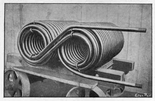
Fig. 54. - Pipe Coil for Refrigerating Machine, Electrically Welded by Thomson Process. Pipes Welded end to end by moving Welding Machine during Operation of Coiling.
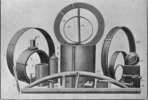
Fig. 55. - Some Applications of Electric Welding (Thomson Process). Samples include Automobile Parts, Bicycle Parts, Steel Tubing welded longitudinally, Stampings welded to Rods and Tubes, Channel Tyres, Baby Carriage Tyres, Cutlery, Cylinders, etc.
"To facilitate the working of electric welding machines on polyphase circuits, Professor Elihu Thomson has recently patented a method of winding the transformers to prevent unbalancing the phases. This will doubtless lead to considerable developments in the near future, seeing that the power companies' supply mains are available in most manufacturing centres."
Electric welding has been in constant operation, for many years, at the works of Messrs. Stewarts and Lloyds, Limited, and has chiefly been employed on large pipes and fittings for high-pressure steam.
The weld is absolutely solid, and exhaustive tests have proved it to be equally as strong as the tube itself.
When it was proposed a few years ago (owing to the increasing steam pressures and temperatures causing trouble with the copper and cast-iron pipes then in use) to adopt wrought-iron or steel piping for steam-pipe installations, great difficulty was experienced in obtaining a thoroughly satisfactory form of flange joint for the wrought piping; and it was not until the introduction by Stewarts and Lloyds, Limited, of their flanges welded solid to the pipe, that the use of wrought-iron and steel steam-pipes became general.
At first the flanges were welded on to the pipe plain ; but subsequently the firm instituted an improvement by perfecting a machine which leaves a large fillet at the root of the flange. This fillet, which gradually reduces the thickness of the metal from flange to pipe, enables both to be brought to a, welding heat and to be perfectly welded without overheating. This operation cannot be satisfactorily performed with plain flanges, nor with those formed with a large boss at back. The improved method ensures a sound weld over the whole area of contact, which, in consequence of the fillet, is about twice as great as it was before the improvement was introduced.
This fillet also gives greater stiffness to the flange and makes the joint thoroughly reliable for the highest pressures. It also enables larger size pipes and higher pressures to be used for hydraulic purposes than formerly.
These welded-on flanges are now being specified by consulting engineers and steam users generally for all high-class work ; and the prices, as a rule, compare favourably with those for inferior types of joints.
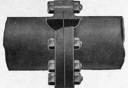
Fig. 56. - Form of Special Facing for Electrically Welded Flanges : Plain Faced.
Pipes with these flanges have repeatedly been tested to destruction, and special tests have been made to satisfy the rigid requirements of the Board of Trade, and also of the Engineering Standards Committee.
As a result, it has been found that pipes of the thicknesses specified in the table given below for 200 lbs. steam working pressure (which carry a factor of safety of nine and over) invariably burst before the flanges show any signs of fatigue. Destruction tests have, in all cases, proved the flanges to be thoroughly welded on to the pipe; and under mechanical tests, the flanges and pipes bent and finally broke, while the continuity of the weld remained undisturbed.
Figs. 56 to 59. - Forms of Special Facing for Electrically Welded Flanges.
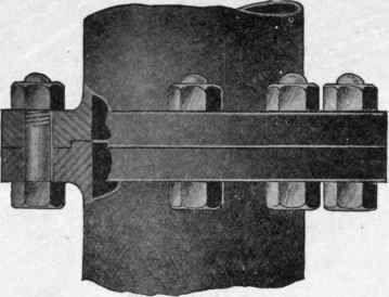
Fig. 57. - Single Spigot and Faucet.
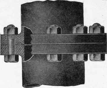
Fig. 58. - Double Spigot and Faucet.
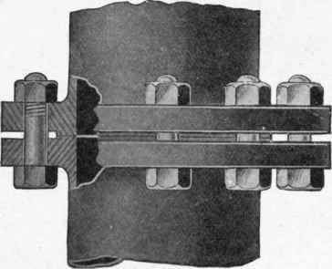
Fig. 59. - Facing Strips.
The tests under the Board of Trade requirements were made to the direction of their inspectors, who, after witnessing the various operations, and having satisfied themselves that the bursting tests of the pipe would not disclose any defect in the flange welds, proceeded to demolish a number of the flanged pipes under steam hammers.
The flanged pipes were divided longitudinally into four pieces, and bent cold to the various shapes, the object being to subject the metal in the neighbourhood of the welds to the greatest possible strain, and in no case was the weld in any way disturbed.
The result of these tests was the acceptance of pipes with welded-on flanges for any work under Board of Trade survey.
The flanges are generally made from wrought-iron, and all facing, edging and drilling is done on up-to-date machines, and the greatest care exercised to ensure a high standard of accuracy.
The joints are, as a rule, faced plain, as Fig. 56. If required, the flanges can be faced either with a single or double spigot and faucet, as Figs. 57 and 58, or with a double spigot as Fig. 59, all of which types of facing are frequently used in connection with high-pressure steam-pipes, and are eminently suitable for use with metal joint rings.
Continue to:
My Books

