


Telephone Circuits And Wiring. IV. Potting up the Line
Description
This section is from the book "Amateur Work Magazine Vol3". Also available from Amazon: Amateur Work.
Telephone Circuits And Wiring. IV. Potting up the Line
ARTHUR H. BELL
In the previous chapters a description of apparatus suitable for operation over a considerable distance. The next matter of interest is the construction of a pole line to carry the two conductors from station to station. It is difficult to give specific instructions for such work because of the different conditions to be met with in various sections of the country, especially as regards soil and climate. But a practical understanding may be obtained from a description of the methods usually followed.
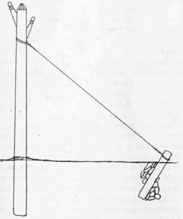
Permanent right of way must be secured in writing from town and citizens for every pole and for the wires and attachments placed thereon, and for the privilege of placing wires and fixtures upon the roofs of disinterested parties. The line should be surveyed as straight as possible, avoiding lengthy curves and wooded sections. One hundred and fifty feet between poles is a fair distance, providing the poles are of a length of twenty to twenty-five feet and set at least about five feet in the ground. On a two wire pole there is no need of cross arms, as insulators may be fastened to the poles, as shown in Fig. 9. On highways, where the wires are to cross from one side to the other, the crossing should be made at an angle of forty-five degrees, and poles should be all of twenty feet above ground, and the sag of the wire should be over eighteen feet from the ground. It may be well to ascertain from town authorities just what rules obtain in the construction of overhead wires. The stoutest poles should be reserved for corners and bends in the road. The top of each pole should be pointed (roofed) and painted. Poles do not require to be set so deep in rocky soil as in mellow earth, in fact, a pole of twenty-five feet length may be firmly set in three feet of rock formation.
In digging post holes it is advisable to dig them large enough to permit the poles to enter readily and to permit tamping. After the pole is in position the earth should be returned a little at a time and tamped firmly on all sides with a log or heavy device designed for the purpose, and the gravel remaining after filling should be evenly banked about the pole. At all corners and curves special attention must be devoted to anchor guys arranged to support the pole in time of storm. Often times the guy wire may be conveniently fastened to a nearby tree trunk or to a stout, low branch, if the tree is of considerable size. But the most complete way is the burying of a large log or other anchoring surface to which may be attached a heavy guy wire. Permission should be secured for the trimming of tree branches likely to strike against the wires, due calculation being made for the "drop " of wet foliage and snow laden branches.
The line wires may be No. 14 copper for very short lines and No. 12 for longer lines. Galvanized iron wire is often used and will answer very well for private line work. Particular attention must be paid by the amateur lineman to foreign wires along the path of his line. The services of experienced linemen will be required where electric light and power wires are to be passed, and under no circumstances should the inexperienced reader attempt to cross such wires alone and unaided by experienced help. Wires from pole to pole should not be stretched taut, but should be permitted to sag several inches.
In tying line wires to insulators the line wire should never be wound round the insulator but fitted into the channel provided in the knob and secured in place by a piece of strong annealed iron tie wire, one end of which passes over the line wire and is twisted in five or six turns, and the other end passing under the line and likewise turned. This makes a secure hold. A great deal of information that cannot be gleaned from publications will be noted should the amateur arrange to meet a construction gang during its new construction work along the road. Neatness in all things is a foremost requisite, and the amateur should arrange his poles perfectly as regards allignment and sag of line, so that his work will in no way become an eyesore in a community.
A considerable profit on capital invested could be made by two or more enterprising amateurs in the operation of a private line between a village centre and the railway station, as in many places the railway borders the outskirts of the settlement, and ten cents is but a small consideration for sending a message of twenty-five words or so instead of a half-hour's drive in all kinds of weather to the freight depot, county store or post-office. If properly constructed such a line need never be out of repair during its first year of existence, and the annual expense of maintenance will be principally in station batteries and possibly a receiver cord or two.
This is a matter that should appeal to scores of readers whose home environments will permit a successful carrying out of such a scheme, and numerous opportunities for such lines are to be found in all sections of this country.
An electro-mechanical governor for steam-electric plants invented by M. Routin of Lyons, consists of a solenoid, magnetized by a few series turns, and a coil Which is in shunt with the generator. The magnetomotive forces of the two windings are opposed, that of the shunt coil, however, predominating in normal conditions. The field switch, the valve mechanism, and a rheostat in series with the shunt coil of the solenoid, are mechanically connected to the armature of the solenoid. The last named switch performs the function of securing the predominance of the shunt-coil of the solenoid for any position of the latter's armature. Assuming additional load to be put on the generator, the armature of the solenoid will drop a certain dittance, because the increased magneto-motive force of the series winding of the solenoid will, by more nearly balancing that of the shunt coil, diminish the strength of the electro-magnet. In falling, the armature will have acted upon the valve gear, at the same time .cutting out resistance from the field circuit of the generator as well as from the circuit of the shunt coil of the solenoid. If the load is taken off, the action is reversed and the armature is drawn higher up into the solenoid, and if a short circuit takes place the series coil largely predominates, the armature is drawn right up and the steam is shut off. If the fuse blows into the generator circuit, the same thing occurs, the shunt coil now being responsible for this.
Continue to:


My Books

