Electric Welding. Continued
Description
This section is from the book "Welding And Cutting Metals By Aid Of Gases Or Electricity", by L. A. Groth. Also available from Amazon: Welding and cutting metals by aid of gases or electricity.
Electric Welding. Continued
The Resistance system of electric welding seems to have been first introduced by Professor Elihu Thomson, in 1877, whilst making some experiments in the laboratory of the Franklin Institute, Philadelphia, discharging a Leyden battery through the fine wire winding of an induction coil. The fine wire thus became a high potential primary, the ends of the coarse wire winding being brought into light contact and welded together, so that it took some little force to separate them. From this early experiment was developed the now familiar "Thomson process." No electric arc is employed, but the heat which effects the welding is solely due to the resistance of those parts of the metal pieces at the contact where they are to be welded together. This resistance is of course extremely low, and the delivery of sufficient energy for heating and welding is the result of the passage of relatively enormous currents. Their potential is only two or three volts, more or less.
The metal pieces to be welded together are held respectively in massive clamps or vices of highly conducting metal such as copper, with a slight portion only of each piece projecting to form the joint. These projections of the pieces are brought together in firm contact, for which purpose at least one of the clamps is made movable toward and from the other, both of them being mounted on a firm support. The pieces having been adjusted to meet in correct relation for the subsequent formation of the weld uniting them, an electric current sufficient in amount to heat the meeting portions of the pieces to the temperature at which they soften and unite, is passed from clamp to clamp, thus traversing the joint and the short projecting portions of the pieces between the clamps. So heavy is the current at command that a solid bar without break spanning the space between the clamps could be heated and melted. The completion of the weld after heating is effected by pressure exerted to force one clamp towards the other, which results in a slight upsetting or extrusion of metal at the weld, called a burr.
For copper a pressure of about 600 lbs. per square inch of section is usual, while with iron it is 1,200, and with tool steel 1,800 lbs. or more.
The welding clamps are in practice carried directly upon the secondary terminals of a special welding transformer.
The various applications of the welding by resistance require different machines, according to the shape and size of the work. Mr. Hugo Helberger has kindly lent some of the following blocks.
The current may be supplied from an already existing generating plant, or a new plant (primary plant) may be erected. The most advantageous form of current is single-phase alternating current; in this case the machines may be connected to the electrical supply as easily as an ordinary incandescent lamp. In the case of two- or three-phase current the machine must be connected to one phase, care being taken that this phase is not overloaded in comparison to the other phases. If several welding machines are required these can be distributed among the different phases, and the use of the multi-phase current presents no difficulties.
In cases where no alternating current is obtainable, only direct current being present, or where no electric current at all is obtainable, a single-phass generator must be installed, or direct welders, which are built as current generating machines, may be used, always assuming the presence of driving power. Direct welders are only built up to 10 h.p.; above this, separate generators must be employed.
Motor-generators may be utilised where direct current is obtainable. The direct current is transformed into a suitable alternating current.
Each welding machine consists of two main parts, i.e., the welding apparatus and the transformer. These two parts are rigidly secured to each other and built as one piece, whereby a higher efficiency is attainable than if each part were built separately.
The welding apparatus is essentially an arrangement of mechanical parts and consists of the contact device, the clamping arrangement and the means for exerting the necessary pressure. Rapid working being the chief advantage of electric welding machines, these devices are generally most carefully constructed, even in the smallest detail.
The construction of the welding apparatus with a view of reducing the time of manipulation to a minimum has caused the welding machines to be subdivided into universal welding machines and special welding machines.
Universal machines are built in such a manner that all kinds of objects can be welded therewith (Figs. 32, 33, 34). In order to increase its practical application the parts as well as the welding apparatus as a whole are made interchangeable.
These machines are chiefly used in constructive iron works, in workshops for architectural and artistic ironwork, and in similar establishments for executing all those kinds of welding work which occur most frequently in such works ; end to end welding ; the welding of pieces at an angle to each other ; the cross-welding of wire, rods, bands, square iron, L-iron and all other kinds of profiled iron and steel. By changing the welding apparatus the machine can be employed for welding of tubes and hoops or rims.
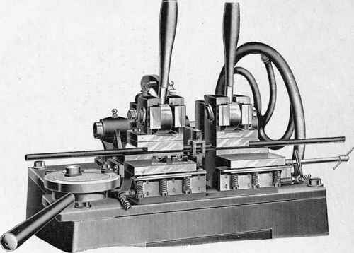
Fig. 32. - Universal Welding Machine for Welding or for Electrically Heating Pieces for Subsequent.
Working, with Swages, Hand-operated.
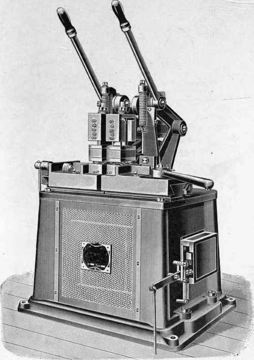
Fig. 33. - Universal Machine, Normal Pattern, without Swages.
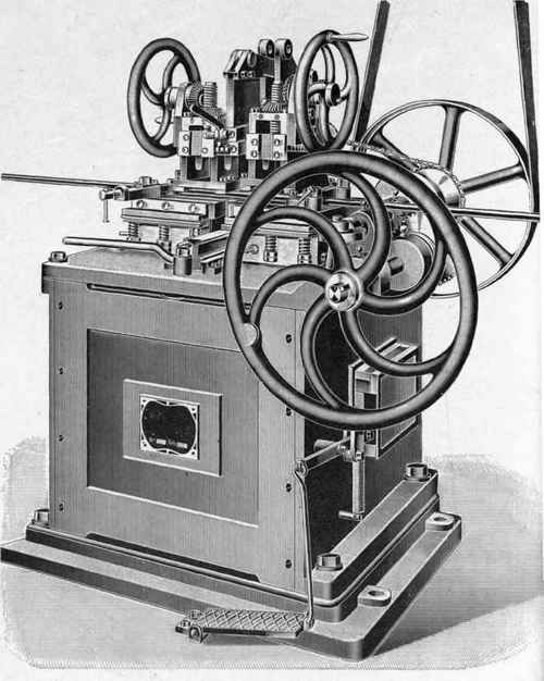
Fig. 34. - Universal Machine, with Automatic Hammer and Adjustable Anvil for.
Continue to:
My Books

