Acetylene Blowpipe. Part 2
Description
This section is from the book "Welding And Cutting Metals By Aid Of Gases Or Electricity", by L. A. Groth. Also available from Amazon: Welding and cutting metals by aid of gases or electricity.
Acetylene Blowpipe. Part 2
Thickness of Plate in m.m. | Size of Blowpipe to use. | Speed of work in foot run of weld per hour. |
1 | 3 | 50 |
1.5 | 4 | 40 |
2 | 5 | 35 |
2.5 | 6 | 30 |
3 | 7 | 24 |
4 | 8 | 18 |
5.6 | 9 | 14 |
7.8 | 10 | 10 |
9.10 | 11 | 7 |
11.25 | 3 A.D. |
The orifice of the nozzle must be constructed accordingly, and the blowpipe must be light and easy to handle.
The velocity of the gas mixture when it leaves the nozzle must not be too great, as it would prevent the controlling of the welded metal with the flame, nor should it be too small, as it would then cause the flame to repel or to be driven back.
With a consumption of 3,000 litres of acetylene per hour, for instance, the working pressure should not exceed three atmospheres, and when the consumption is smaller it should be reduced accordingly, even to 0.5 atmosphere. The velocity of the gas would in such a case not exceed 250 metres per second.
A constant gas consumption, combined with a constant pressure and the largest orifice possible of the nozzle, constitutes the best burner.
It is evident, therefore, that the construction of a blowpipe must in the first instance be based upon theoretical principles, and the wide range of its application adds considerably to the difficulties of its construction.
The more exact and minutely correct in its construction the more will the blowpipe comply with the theoretical conditions, and the more perfect will be the weld.
Fonche has complied with these conditions by producing twelve different sizes of blowpipes of such a correctness that only can be produced with the most sensitive instruments. Other systems are generally satisfied with four or five different sizes of blowpipes for doing the same work, pointing out this as a great advantage by reason of saving expense to the welder. There is nothing to prevent a reduction in the number of sizes of the Fouche blowpipes, but this could only be done by raising the working pressure in order to increase the working effect, which would result in an unsatisfactory weld.
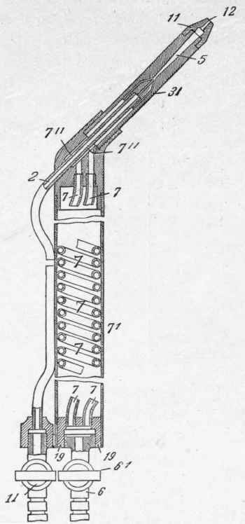
Fig. 85. - Fouche Blowpipe.
A greater volume can certainly be obtained by working with a greater gas pressure, but the velocity of the gas mixture at the egress of the nozzle must remain unaltered. This is only possible when the oxygen injector and the mixing chamber as well as the orifice of the nozzle are all simultaneously altered. But the most important is that the mixture of the gases remains constant and does not decompose in any way.
The unavoidable heating of the blowpipe by radiation of heat from the welding pieces will act differently upon the oxygen, which is introduced at a high pressure and in a constant quantity, and on the acetylene, at a low pressure, and will cause, after a few minutes' working, an alteration in the composition of the flame, which will become more and more rich in oxygen with corresponding oxidation of the welding metal. An attentive and skilful welder can notice these effects from the appearance of the flame, and will therefore stop the welding in order to cool the blowpipe or change the nozzle. The Fouche blowpipe, 1908, avoids all these disadvantages mechanically, and retains absolutely the reducing property of the gas mixture, while its weight is only one-third of that of the former construction (Fig. 85).

Fig. 86. - Fouche Cyklop Blowpipe.
The following table shows the approximate consumption of acetylene by the various sizes of Fouche's low-pressure blowpipes, 1908, for different thicknesses of plate : -
Fouche Blowpipe.
No. of Blowpipe. | Thickness of Plate in mm. | Consumption of Acetylene in litres per hour. |
2 | 0.5 | 36 |
3 | 1. | 75 |
4 | 2. | 130 |
5 | 3. | 210 |
6 | 3 - 5 | 300 |
7 | 5 - 7 | 450 |
8 | 7 - 10 | 650 |
10 | 10 - 13 | 1000 |
12 | 13 - 16 | 1500 |
15 | 16 - 25 | 2200 |
Fouche Cyklop Blowpipe. - Fig. 86.
No. of Blowpipe. | Thickness of Plate in mm. | Consumption of Acetylene in litres per hour. |
2 | 0.5 | 36 |
3 | 1. | 75 |
4 | 2. | 100 |
5 | 3. | 150 |
6 | 3 - 5 | 225 |
7 | 5 - 7 | 350 |
8 | 7 - 10 | 500 |
10 | 10 - 13 | 750 |
12 | 13 - 16 | 1000 |
15 | 16 - 25 | 2000 |
16 | 25 - 30 | 2500 |
In workshops where various welders are engaged, it is advisable to have several blowpipes, but where repairing work is principally being done, or where one welder only is operating, a Fouche Gigant blowpipe would be the best to use.
In the Fouche Gigant, the oxygen injector, the suction, nozzle and the head of the blowpipe form all one solid piece which may be removed in one single operation; while in other similar burners the nozzle only and not the oxygen injector is generally exchangeable. The most favourable velocity of the gas mixture, and consequently also the rational working, is thereby secured; any confusion in employing a wrong nozzle is prevented and thus waste of gas avoided.
Fouche Gigant No. 1, with five exchangeable parts, represents the blowpipes Nos. 2, 3, 4, 5 and 6; Fouche Gigant No. 2, with six exchangeable parts, the blowpipes Nos. 4, 5, 6, 7, 8 and 10; Fouche Gigant No. 3, with three exchangeable parts, the blowpipes Nos. 12, 15 and 16. The Fouche blowpipes can be used either for low or high pressure.
Dr. Michaelis gives the sizes of the piping between the gasometer and the weld by Fouche's blowpipe as follows: -
Distance in Metres from Gasometer to weld. | Quantity of Acetylene required per hours in litres. | |||||||
80 | 100 | 200 | 300 | 500 | 1000 | 2000 | 3000 | |
Internal diameter of pipe in m.m. | ||||||||
10 | 10 | 10 | 10 | 13 | 20 | 20 | 26 | 32 |
20 | 10 | 10 | 13 | 13 | 20 | 26 | 32 | 32 |
30 | 10 | 10 | 13 | 20 | 20 | 26 | 32 | 40 |
40 | 10 | 10 | 13 | 20 | 20 | 26 | 32 | 40 |
50 | 10 | 10 | 20 | 20 | 20 | 26 | 40 | 50 |
75 | 10 | 13 | 20 | 20 | 26 | 32 | 40 | 50 |
100 | 13 | 13 | 20 | 20 | 26 | 32 | 40 | 50 |
200 | 13 | 13 | 20 | 20 | 26 | 40 | 50 | 60 |
500 | 20 | 20 | 26 | 26 | 32 | 40 | 60 | 80 |
1000 | 20 | 20 | 26 | 26 | 40 | 50 | 60 | 80 |
w.
M
Fig. 87 is an illustration of a complete low pressure oxy-acetylene plant without the acetylene generator, which may be placed in any suitable position, preferably outside and at any distance from the blowpipe, and its connection with the blowpipe.

Fig. 87. - Low-pressure Oxy-acetylene Plant, without the Generator.
A is a tap connecting the inlet to the hydraulic safety valve with the acetylene supply pipe from the acetylene apparatus.
The blowpipe is connected at a by means of an ordinary stout rubber tube with the outlet tap B of the hydraulic safety valve. This forms the acetylene supply pipe to the blowpipe.
The blowpipe is connected at 0 by means of a special canvas-covered strong rubber pipe with the outlet tap T of the oxygen pressure regulator, which is fixed, as shown, on the oxygen cylinder.
This pipe conveys the oxygen supply to the blowpipe, and should be securely attached, as it is subject to pressures varying from 10 lbs. to 20 lbs. per square inch.
Continue to:
My Books

