


Chapter IV. Various Methods Op Joining Timber
Description
This section is from the book "Our Workshop", by Anonymous. Also available from Amazon: Our Workshop.
Chapter IV. Various Methods Op Joining Timber
THE practical carpenter displays his skill by the judicious choice of that form of connection which will, with the least waste of material, insure the firmest junction of the pieces to be united. He has, moreover, carefully to consider the intensity and direction of the strains tending to rupture the material and separate the joints.
The amateur being principally interested in the construction of light works, it will be unnecessary to investigate very deeply the formation of heavy framing: we shall therefore only notice a few of the most important connections in general use.
When it is necessary permanently to lengthen a beam, another of similar scantling is pieced on to it. There are many methods of "piecing" or scarfing timber, and every carpenter has his own nostrum, which he considers superior to all others. Considerable ingenuity is often displayed in the various connections required in massive framings, such as roofs, etc, but it is generally found that the simpler forms of attachment are quite as strong as the more elaborate.
The simplest and probably the strongest way of piecing a beam, is to lay the end of one for a certain length over that of the other, and connect them firmly by bolts, which must pass through both timbers. This form of scarfing is certainly clumsy and unartistic, but it is a cheap and serviceable connection, and very good in situations where great neatness is not required.
The next, and probably the most usual kinds of piecing, are shown in fig. 27. In A, the two scantlings to be united are "halved together" by cutting away half the thickness of each of them for the length of the joint, so that when bolted together the beam may appear as one unbroken length. The iron plates are only required at the two extremities of the scarf to keep the ends of the respective timbers from springing under heavy strains. It is necessary to place large iron washers under the nuts, to enable us to screw them up tightly without cutting into the wood.


Fig. 27.
The form of scarfing represented at B is not so capable of resisting a crushing force as A, which is more suitable for a pillar than B, owing to the support derived from the shoulders, s s. If B were used in a situation where it had to withstand a crushing strain - which tends to force both ends of the beam towards the centre - the wedge-shaped ends would be liable to slide on each other, and the thin tongues, t t, which confine their extremities, would, owing to the pressure, be apt to split off.

Fig. 28.
Another method of scarfing is shown in fig. 28. In C the timbers are "halved together" in a somewhat similar manner to A, fig. 27, but the bolts and plates are omitted. The end of each beam has a "rebate," r r, formed on it, which locks into a corresponding "groove" made in the shoulders. Two keys, k k, having a slight taper, are driven in to draw the neighbouring parts of the joint closely together. One key in the centre would be equally effective, provided it were made a little wider. This form of connection is capable of resisting either a crushing or a tensile strain, and may be considered the best of the more complicated varieties of piecing. D is not so good, having the same defect as B, fig. 27; and if it were used as a pillar, its strength would be very inferior, owing to the absence of bolts, which are almost necessary in this kind of joint.
If unassisted by iron plates, no form of scarfed tie-beam can possess more than one-third of the strength of the solid beam; and it must be remembered that the strength of any joint or framing can never exceed that of its weakest part. A very simple kind of scarf much in favour amongst shipwrights is shown in fig. 29, and is termed fishing a beam. Two beams of similar scantling are brought end to end, and two pieces of wood, each about half the thickness of the beams, are placed on their opposite sides; the whole is then strongly bolted together. This form of joint is very strong, especially as a post, and it is a ready and effective method of making repairs.

Fig. 29.
Dovetail connections, as shown in fig. 30, and at E E, fig. 31, are sometimes employed for posts, but they cannot be recommended, and should not be used without plates and bolts, if the weight to be supported is great. Dovetail joints are seldom introduced into heavy carpentry works, even when the grain of both pieces runs in the same direction, as in figs. 30 and 31. When half the thickness of each piece is removed, as at r r, fig. 31 (left-hand figure), and the cut surfaces are brought together, it is called a lapped joint. If the timbers be laid so that the grain crosses at a considerable angle the dovetail should not be used, as the shrinkage of the wood will cause the joints to become loose; therefore, D, fig. 32, would be objectionable in a situation where the joint was subjected to even a moderate strain. When the timbers cross at an angle of forty-five degrees they may be united by "halving," as shown at H' H. The method is slightly different in H', where the timbers meet at the ends, and form a corner.

Fig. 30.
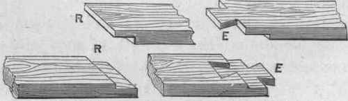
Fig. 31.
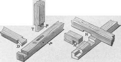
Fig. 32.
When one timber abuts against another the joint is made as shown at T, in fig. 32. The piece T is called the tenon, and the hole, m, which is to receive it the mortise. The tenon must fit the mortise closely, and its shoulders must rest fairly on the surface of the wood against which it abuts. An oak pin is usually driven in at p, to secure the tenon, as it is liable to draw back; the strain should tend to keep the shoulder of the tenon in contact with the wood in which the mortise is made.
The ordinary form of mortise and tenon employed in heavy carpentry is shown to a larger scale in fig. 33. The tenon, T, should seldom exceed one-third of the thickness of the stuff, otherwise the piece containing the mortise, M, will be weaker at that part than the tenon. The endeavour should always be to balance the strength of the two parts, so that, if subjected to a severe strain, they would yield equally. The tenon is formed by cutting away one-third of the thickness of the timber on each side of it, and as the work will receive no further finish than is imparted by the tenon-saw (fig. 34), this tool must be exceedingly well applied to insure a good fit in the mortise. The method of cutting the mortise will be explained hereafter.
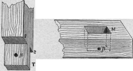
Fig. 33.

Fig. 34. - Tenon-saw.
After the tenon has been driven home, so that the shoulders, s s', bed fairly on the surface of the wood around the mortise - in which they will fail if all the parts be not exactly square - the hole, p p' must be bored, but rather smaller than it will ultimately be required. The tenon must then be withdrawn from the mortise, and the hole, p' be enlarged to the proper size for the pin; p must also bo increased to the same size, but its centre is removed a trifle towards the shoulders, s s', so that when the tenon is reinserted in the mortise, the holes, p p' will not exactly tally. The discrepancy should be very slight, otherwise the tenon may be split when the pin is driven home. By setting the hole in the tenon a little behind that in the mortise, the pin is enabled to draw the tenon forward until both the holes correspond, when the shoulders, s s', will bear firmly on the surface, M.
Sometimes the tenon is brought boldly through the mortise, and the pin passed through its extremity. Square pins are used in this situation, being considered less liable to split the end of the tenon. If the end of the tenon be chamfered and the workmanship is good, this form of joint is not unsightly, and is frequently introduced in situations where the joint is exposed to view.
We shall have occasion to speak further of the formation of the tenon and mortise, the dovetail, and some other connections, when explaining the use of the tools employed by the joiner.
Continue to:


My Books

