


Of The Pressure Of Inclined Beams
Description
This section is from the book "Elementary Principles Carpentry", by Thomas Tredgold. Also available from Amazon: Elementary Principles Of Carpentry.
Of The Pressure Of Inclined Beams
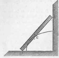
35. Let A B (Fig. 22) be a beam resting against the vertical wall B D, and C its centre of gravity; the lower end resting on an abutment cut in the beam A D. Through the centre of gravity C, draw the vertical line c e; and draw c B perpendicular to B D, meeting c e in c. Join Ac, which will be the direction of the pressure against the abutment at A; and that the beam may have no tendency whatever to slide, the abutment should be perpendicular to Ac.
Also, if c e, taken from a scale of equal parts, represent the weight, and a e be drawn parallel to c B, then a e will represent the pressure against the wall at B, and ca the pressure against the abutment at A. The horizontal thrust at the abutment A, is also measured by the line a e; as it is always equal to the horizontal pressure against the wall at B. The pressures of shed or lean-to roofing are shown by this example.
Fig. 22

36. Let A D (Fig. 23) be a smooth horizontal plane, and BD a smooth vertical plane; the force which the end A, of the beam A B, would exert in a horizontal direction in any position of the beam, may be found by the equation Wxm cos.a/h=the horizontal thrust. Where W is the weight of the beam, m the distance of the centre of gravity A C from the lower end; a the angle which the beam forms with the horizon; and h the height B D of the upper end of the beam.
It is evident from this equation, that when the weight is the same, the length of the beam does not alter the horizontal thrust, while the angle of inclination and distance of the centre of gravity are not varied; and that the horizontal thrust increases in proportion to the distance of the centre of gravity from the lower end, and that it also increases as the angle of inclination decreases.
37. It has been already stated, that the abutment should be perpendicular to the direction of the pressure (Art. 35); and it may be shown that the tangent of that angle which the abutment for the lower end should form with the horizontal plane is equal to mxcos.a/h which becomes AD/2h when the centre of gravity is at the middle of the length of the beam. Hence the angle may be easily calculated.
38. When the beam moves between the planes, so that the lower end slides along the plane A D (Fig. 23) and the upper end down the plane B D, the point C opposite the centre of gravity will describe a portion of an ellipse of which B C will be the semi-transverse, and A C the semi-conjugate axis. And when the centre of gravity is in the middle of the length of the beam, it will describe a circle; of which the radius is equal to half the length of the beam. This curious property may in many cases be applied to describe an ellipse on a large scale with advantage, as it is simple and easy to put in practice almost in any situation. The line in Fig. 23 shows the part of an ellipse so described.
Fig. 23.
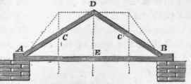
39. When two similar and equal beams A D and D B are placed in the position represented in Fig. 24; CC being their centres of gravity; then their pressures against each other, at the point where they meet, will be equal and opposite; and their horizontal thrusts will also be equal, and may be found by Arts. 35 and 36; as each beam is obviously in the same state as that in Fig. 22.
The horizontal thrust of a roof is nothing more than a particular case, to which the foregoing rules apply. The equation in Art. 36 is given in words at length, with an example of its application to that purpose.
40. Rule For The Horizontal Thrust Of An Inclined Beam
Multiply the weight in pounds by the cosine of the angle of inclination; and multiply this product by the distance, in feet, of the centre of gravity from the lower end; divide the last product by the height D E in feet, and the quotient will be the horizontal thrust in pounds.
Example. - Let the weight diffused over the length of a rafter be 1600 lbs.; the angle of inclination 27 degrees, of which the cosine is .891: and the distance of the centre of gravity from the lower end, 7 feet; the rise or height D E being 6 feet 6 inches, or 6.5 feet.
Fig. 24.
Then, 1600x.891x7/6.5 =9979.2/6.5 = 1534 lbs. nearly for the horizontal thrust, which is not much less than the weight in this particular case.
When the centre of gravity is at the middle of the length of the rafter, the rule becomes more simple, and may be stated as follows: -
Rule, when the centre of gravity is at the middle of the length of the rafter or beam. Multiply the weight in pounds by the distance A E, in feet (which in a roof is half the span), and divide the product by twice the height D E, in feet, and the quotient will be the horizontal thrust.
Example. - The weight uniformly distributed over a rafter is 200 lbs.; the span of the roof is 20 feet, half of which is 10 feet; and the height of the roof is 5 feet. Then,
200x10/2x5 = 200 lbs. the horizontal thrust, which is exactly the same as the weight, and will always be so when the roof rises one-fourth of the span, but not in other cases.
41. Let us now suppose a weight to be laid on at D,in Fig. 24; its effect would be to press the beams in the directions of their lengths, as has been shown, and the magnitudes of these pressures may be found by the former articles (see Arts. 6 and 14). Hence we see that a beam performing the part of a strut or an oblique support is often strained by two forces, the one being caused by the weight supported, and the other by the weight of the beam itself, or some uniform load. But it is a well-ascertained fact, that a beam pressed in the direction of its length is very much weakened by a cross strain of this kind. If a beam happens to have a slight natural curvature the convex side should be placed upwards, which will counteract the effect of the weight of the beam.
42. It is easy to alter the directions of the pressures of a beam by altering the position of the supporting surfaces. If, for example, the beam A B (Fig. 25) were cut so as to rest upon two level plates at A and B, the beam would have no tendency whatever to slide, notwithstanding its inclined position, and consequently it would have no horizontal thrust. The carpenter may in many cases take advantage of this circumstance in preventing oblique strains upon the points of support, for those supports may be abundantly strong to resist a perpendicular pressure, and yet be incapable of sustaining a very small force in an oblique direction.
The present example shows that by cutting the rafters of a shed roof so that they may rest level upon the plates, the roof will have no tendency to push out the lower wall.
43. To find the perpendicular pressure upon the points of support, draw the horizontal line a b through G the centre of gravity of the beam.
Then, WxbG/ab is equal to the pressure on A,
And, WxaG/ab: is equal to the pressure on B;*
Or, as b G: a G:: pressure on A: pressure on B.
The perpendicular pressures upon the points of support when the beam is horizontal, as in Fig. 26, may be found by the same rules.
When two or more weights are unequally distributed, the pressure on each point of support is equal to the sum of the pressures of each weight taken separately and found as above.
Fig. 25.
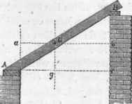
Fig. 26.

* Gregory's 'Mechanics,' vol. i., art. 80.
Continue to:


My Books

