


An Automatic Duplex-Connected House Pump
Description
This section is from the book "American Plumbing Practice", by The Engineering Record. Also available from Amazon: Plumbing: A working manual of American plumbing practice.
An Automatic Duplex-Connected House Pump
(Published In 1894.)
In the residence of J. Pierpont Morgan, Esq., at Fifth Avenue and Thirty-ninth Street, New York City, the extensive plumbing system has been installed for years and includes pump connections for the water supply to the lower floors, roof tank, and elevator service. The general features of the original pump arrangement are conventionally indicated in the diagram, Fig. 1, which shows a hot-air pump connected up to be supplied either from the city mains direct or from the surge tank that receives the water discharged from the elevator cylinders, and to deliver correspondingly either to the house supply tank or the elevator pressure tank, both on the roof. The operation of this system, like all other double systems, requires accuracy and attention for the valves, which must always be correctly manipulated and individually changed whenever the pump service is varied. To pump into the house tank, valves B and E were opened and valves D and F were closed. To pump into the elevator tank the oily water that had already been used there, valves E and B were closed and F and D opened. Valves D and F were to be opened only when the elevator tank was to be filled.
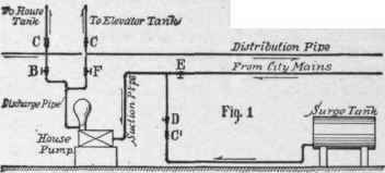
As the control of these four valves developed upon servants who were likely to be careless or ignorant and negligent, and might often be replaced by newcomers, there was always danger of improper manipulation. It was found that the surge tank was sometimes overflowed by city water, and that the dirty water from the surge tank was at other times distributed throughout the house. Check valves C C, opening upwards, were accordingly put on the tank pipes, but of course had no effect except to relieve the pump valves. Considerable difficulty continued to be felt, and Spellman & Blair, of New York City, were employed to remedy it. They first put on a check valve C, opening up, so as to prevent water from the city pipes overflowing the surge tank if valve D should be left open. But this did not prevent the possibility of pumping from the surge tank into the house system. One day when both tanks had been filled and the pump was under full headway the servant closed all its valves and it immediately burst, making a complete wreck. To prevent the possibility of a repetition of this accident and to avoid confusion with the two systems of suction and delivery it was advised to use two separate independent pumps. But Mr. Spellman objected to this and devised an arrangement for automatically operating both services with one pump without danger of mixing the water or possibility of impeding the discharge.
An Otis electric pump No. 3 was put in and fitted up as shown in Fig. 2, with its suction and discharge pipes connected to a special valve A, which consists substantially of two three-way cocks operated simultaneously by one handle H. These cocks are separate and independent except that they are so connected that they must both be operated together by the connecting spindle S, which makes the house tank and city supply pipes register with the pump delivery and suction ports, and closes the surge tank and elevator pressure tank pipes, or vice versa.
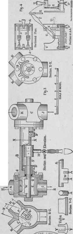
Figure 3 shows the details of the valve, which consists essentially of twin chambers C C, connected by a body B and operated by a spindle S, which is commanded by a lever H. The valve is entirely of brass, with ground joints at G, capstan-headed stuffing-boxes D D, asbestos packing E, and holding rings Q. The spindle S is jointed in the middle, where it is riveted to the lever head, and it has at each end a wing W, over which the ground valve V slips freely and is snugly seated by the pressure of two spiral springs A A. The pump suction and the delivery pipes are screwed on at I and J, and their ports are always open into the chambers, which have discharge and delivery pipes screwed an at K K K K with their ports P P' commanded by valves V. The length . M of the face of the valve V is made exactly equal to the distance N between ports P and P; so that, in changing from one system to the other, when the valve V is revolved to position V port P begins to open as soon and as fast as port P' closes and there is always a full area of discharge ports open under all possible circumstances. When lever H is horizontal, as shown in Fig. 2, the pump is connected to city main and house tank. When it is pulled down to H' the pump is connected to the surge tank and the elevator tank. As the house tank requires filling two or three times a day and the elevator tank only about once a week, the valve is left set open to house connections, and a card affixed directing the handle to be depressed to fill the elevator tank, and then raised and left in its former position; and the pump can only be stopped by replacing the lever in its horizontal position.
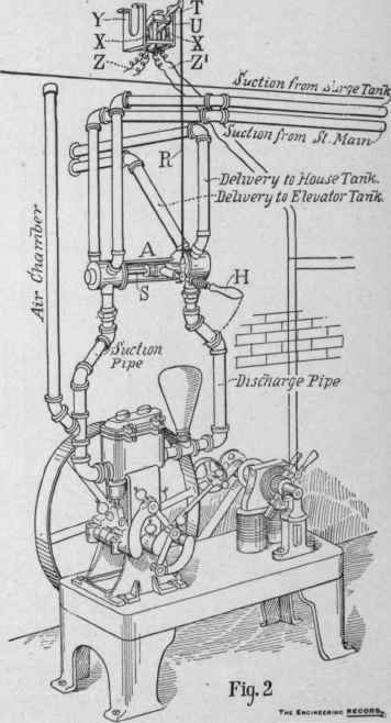
The electrical connections are so arranged that when the water in the house falls to a certain depth its float operates a switch and turns the current from the street main into the motor circuit and starts the pump, breaking the circuit and stopping the pump when the float rises to the top of the tank, thus making the house service automatic. When the handle H is depressed to connect the pump to the elevator pipes, its attached rod R pulls down the lever T and makes a contact between the copper bars U U and the posts X X, which completes the circuit between the main line wire Z and the pump wires Z', and thus starts and stops the pump by opening and closing the elevator valves. Y is merely a brass frame by which the elevator switch is supported from the ceiling.
Figure 4 shows the details of the switch open, the valve making connections for the house tank. Reversing the valve so as to make elevator connections makes rod R pull handle T down to T' and closes the circuit between the main wires Z and the pump wires Z' through copper bars U U and posts X X. The operation of this valve and pump system has proved convenient and satisfactory. The designers believe it to be complete and reliable and well adapted to conditions where two different services are required from the same pump, and that it is the first instance where a house pump has been connected to two suctions and two discharges controlled by a single valve. The house tank was originally arranged to be filled as fast as the water fell 8 inches from the high-water tank, but by suspending its float weight by a spiral spring the motion of the exterior lever is reduced one-half and the pump only operates for a fall of 16 inches in level. As first arranged the elevator-tank float was made to operate at low water an electromagnet that exerted sufficient pull on the valve handle H to pull it down and open.the elevator ports. When the tank was full the handle was released, allowing a counterweight to return it to its original position. As this arrangement made the entire system automatic, it was feared that no attention would ever be paid to the machinery, so it was made to require personal attention about once a week when the low-water alarm sounded for the elevator tank, and the attendant is thus reminded to clean and oil the pump.
AN AUTOMATIC DUPLEX-CONNECTED HOUSE PUMP.
Continue to:


My Books

