


Tool Making For Amateurs. VII. A Grinder Head for a Lathe
Description
This section is from the book "Amateur Work Magazine Vol4". Also available from Amazon: Amateur Work.
Tool Making For Amateurs. VII. A Grinder Head for a Lathe
ROBERT GIBSON GRISWOLD
To the amateur, fond of doing fine mechanical work, there is nothing that appeals so strongly as a finely finished piece of work or an absolutely accurate fit. But such accurate work demands very accurate tools. The ordinary lathe tools are not capable of doing very close work, especially when the finish is made with a file : but if work is finished to within .003 of an inch with a tool and then brought to size by grinding, a very accurate piece of work may be obtained.
In fact, there is scarcely any limit to the nicety with which a definite size may be obtained on cylindrical forms, and one may, with a little practice, come within .0001 or .0002 in. of a given size, while an absolute diameter, as measured with a micrometer, is quite as readily obtained,
Most of the grinding done in commercial lines is accomplished by means of special machines, the truth and accuracy of which is almost beyond criticism. But if the ways of a lathe are in good condition a very fair class of work may be done, and far ahead of any hand finish that can possibiy be given. The thought generally arises in the mind that grinding is a slow and tedious process, but in all probability this is due to the fact that the wheel apparently removes little material at a time. But such thoughts are fallacies. A perfectly true-to-size piece may be secured in far less time by grinding than by any other method, and that with absolute certainty as to its being straight.
Most of the appliances used in lathe grinding are more or less crude, especially what is known as the " tool-post" grinder. This is through no fault of the no fault of the machine, but due to an accumulation of possible errors. In the first place, the cross feed screw of any lathe is not fine enough to secure cuts varying from .0001 in. to .0005 in., and unless this is possible little can be done towards really accurate work. Then again, the wheel is generally overhung on parallel bearings, seldom adjustable. In grinding to a shoulder, parallelism of the wheel with the plane of the shoulder is dependent only on the accuracy of the tool-post seat and bottom of the grinder stock. Too often the grinder is made interchangeable with an inside grinder ; this should never be, for the simple reason that the requirements of the two are so entirely different and the speeds so varying, that of an inside grinder being fully five to ten times that of an outside grinder. The bearings required by the two shifts are very different.
Another feature that is absolutely essential in any good grinder is rigidity, and that can hardly be possessed by a greatly overhung wheel supported by a simple fork, as generally used in the tool-post style.
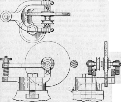
The desire to make a grinder head for a lathe that would overcome these bad features has led to the design shown in Fig. 1. Every part has been given sufficient rigidity and weight to overcome vibration, which would result in chattering and a rippled surface on the work. The adjustment of the wheel feed is so sensitive that .0001 in. or less may be very easily secured, while the coarse feed may be had by the carriage screw. The head is also adjustable to any angle, so that surface grinding may be done on the face plate. The wheel is supported on a hardened steel shaft running in hardened steel bushings, thus giving the minimum amount of wear. The bearings are adjustable and carry the tapered journals of the wheel shaft. This adjustment is absolute and the very best that can be secured for such high-speed, and at the same time, light work.
The base is provided with a body that can be trued on an arbor so that it will bear evenly on the tool-post seat. A ball passes through the center into a nut in the "T" slot, a slight turn on which securely fastens the grinder in any desired position. A lug extends from one side carrying the adjustable screw, and a very heavy, substantial fork carries the wheel yoke. The adjusting screw should be provided with very fine threads, say 40 the inch, and the thumb nut should have a spherical seat washer under it to accommodate every motion of the arm, although small. The spring should be of No. 14 piano wire and very stiff. Drill the cups for the pointed trunion screws very accurately in the lathe. Best done by laying off carefully and then drilling between centers with a very short, stiff drill held in a chuck. Grind the drill to the same angle as the screws, about 60°.
The yoke carrying the wheel spindle is given a form best adapting it to resist the spreading strain of the trunion screws, but as these should be just brought to firm bearing, no great strain need be imposed, as the weight to be carried is comparatively small and the wheel strain very slight. The positions of the various screws are laid off and accurately drilled between centers, as described above. Mount the yoke on its trun-ions and clamp to the lathe carriage, the base of the head having been so machined as to bring the center of the wheel spindle directly in line with the lathe centers. Then sharpen a 3/8 in. drill and mount in a drill chuck so that it runs perfectly true. Now feed the carriage along very slowly so that the drill will drill a smooth, true hole through each arm of the yoke. This insures the parallelism of the lathe centers and wheel spindle, since the holes have been drilled in place. If a | in. reamer is at hand, use a drill about 1-64 in. under size and ream the holes true. The adjusting arm should be clamped down tightly on a small block cut to the proper length to hold the arm in its middle position while drilling. The spring might not be sufficiently stiff to keep the drill from " walking ". The bearing is now split on one side with a fine saw, and this serves to clamp the bushing firmly in place.
The bushings are turned out of a piece of | in Stubbs' steel drill rod. The spindle may also be turned from the same, but it would be better, if a very fine job is desired, to make two spindles, mounting the wheels on one finished as nicely as possible by hand and then grinding the other, after hardening, to a true cylinder and the journals perfectly in line. These journals have a taper of 1/8 in. per foot. The bearings can be made by reaming out the hole with a reamer turned to the taper of the journal. To make this reamer, turn a piece of tool steel to the proper taper and then file away one side until the flat surface coincides with the center line. This leaves a cutting edge on either side, and it will ream a very smooth hole. Harden and grind on the flat side only.
Harden the bushings and lap the hole out with a piece of copper (held in the chuck) turned to the proper taper and charged with flour of emery and oil. This will give a beautiful surface and the bearing will be truly conical.
The spindle is slightly longer than the distance between the arms of the yoke, owing to the desire te get the supports as near :the wheel as possible and this necessitates canting the spindle and putting in first one end and then the other, afterwards inserting the bushings. But as the head is seldom taken apart except for the removal of a broken or worn out wheel, this does not mean much in the matter of time, and it does allow a solid support for the bushing, which is a point greatly to be desired. The head of the adjusting screw bears on one edge of the bushing, and a fine adjustment is secured by screwing these in as wear takes place.
Oil holes are drilled in the top of the bushings and covered with a small ring of brass to exclude dust and small particles of abrasure. A small washer of felt should be inserted in the hole at the end of the bushing, acting as a plug and oil reservoir.
The pulley and clamping flanges need no description excepting that they are secured to the spindle by a spur, the hole for which is drilled in the spindle be-fore hardening. The emery wheel should be about 3 in. diameter and not over 3-16 in. or 1/4 in. thick, and what is known as '• Grade No. 60 or 70." The speed at which a 3 in. wheel should run is about 6500 revolutions per minute, but on foot power lathes this may be difficult without an overhead shaft and light driving wheel, which will be described in the next chap" ter.
At that time there will be described an inside grinder and the overhead hangers and shafting necessary for driving the wheels, to be followed by chapter on grinding, selection of wheels, speeds, etc.
Continue to:


My Books

