


Design For A Light Gasolene Car. Continued
Description
This section is from the book "Amateur Work Magazine Vol3". Also available from Amazon: Amateur Work.
Design For A Light Gasolene Car. Continued
J. C Brocksmith. M. E
Reprinted by Special Arrangement with the American Electrician.
The crank shaft is shown in Fig. 9. This is preferably made from a solid open hearth steel forging, the cranks being cut from the solid metal. Figs. 10 and 11 show respectively the top and bottom halves of the crank case. These are intended to be cast in aluminum alloy containing about 25 per cent zinc. The halves should be planed and carefully surfaced where they bolt together; this joint should be perfectly gas tight, and it is preferable not to use packing but to rely on the surfacing and the bolts for drawing the parts in close contact.
Fig. 12 is a detail of the contact maker for use with jump spark ignition. A spark is required in each cylinder once in each revolution, and since the cranks are at 180° the contacts are also arranged 180° apart. The plate upon which the contacts are mounted is bored for and centered upon the main bearing boss. The plate may be made of aluminum or brass and only the stationary contact need be insulated from it. That is to say, the spring blades are grounded on the engine frame, which is a necessary part of the scheme of connections.
Fig 13 is a diagram of connections of the sparking apparatus. A separate coil is required for each cylinder. For spark coils and plugs the builder will do well to purchase standard articles. Also in regard to the carburettor, it is probable that more satisfactory results will be obtained from a ready-made article than from one of the home-made variety.
Fig. 14 shows the details of the motor fly-wheel and clutch. The wheel is of ca6t iron and is to be turned all over, the inner surface of the rim to be finished to a 15° taper and forms the female portion of the cone clutch. The male portion of the clutch is a disc of aluminum alloy faced with leather and riveted to a steel centre which is bored to fit the reduced end of the crank shaft. A spiral spring forces this disc into contact with the fly-wheel surface, so that the cones are always in engagement except when the clutch pedal is depressed while changing from one gear combination to another. The spring pressure thu6 applied is entirely self contained and does not produce aay end thrust upon the motor or change gear bearings, due to the fact that the fly-wheel is covered by a cap which takes care of this thrust and at the same time forms a dust proof cover for the parts. In order to disengage the clutch the shaft carrying the male cone must have an endwise motion of about 1/2 in., which is allowed for in the jaw clutch that connects the motor shaft to the speed change gear.
Fig. 15 shows the speed change gear, with the top half of the case removed to make clear the arrangement of the gears and their operation. The driving shaft is round and has secured to it by means of pins four gears of different diameters. The driven shaft is ' square and has mounted upon it a spider carrying three gears of suitable diameters to mesh with the gears on tue driving shaft. The spider may be slid endwise along its shaft so that any desired pairs of .gearsmay be engaged. The drawing shows the gears engaged for the flrst forward speed, which gives the highest ratio of engine turns to rear wheel revolutions. The reverse speed gives the same ratio as the first forward speed except that an idler gear is interposed between the driving and driven shaft, thus changing the airec-tion of rotation. The reverse gear is obtained by moving the gears to the left of their position in the drawing, and the two other forward speeds are obtained by moving the spider to the right of its present position. The centre lines at the extreme right of the figure indicate the exact distances through which the shifter rod must be moved to get the various combinations. The universal joint which transmits the motion to the rear axle gear and also in the brake drum are shown in this view. The accompanying table gives the data for gear ratios and sizes of gears for various combinations:
Fig. 16 is atop view of the complete gear and case, showing the length of arms for bolting to the frame work of the car, the 6hifter rod, brake drum, removable cover and universal joint. Fig. 17 is an end view of the gear case, which helps to make clear the position of the idler gear by means of which the reverse speed is obtained. It also shows the screw plug at the bottom of the case, through which the old oil may be drained off. The case should always be partly filled with a heavy oil and the gears and bearings are then lubricated automatically. The best practice indicates that all gears should be cut from machine steel, have the teeth rounded or beveled on the edges, and then case hardened. If for any reason this is impracl ticable, phosphor-bronze might be used, though it wil not, of course, wear as well. Cast iron is, of course, out of the question, as it is so brittle that the teeth would be likely to strip in changing speeds.


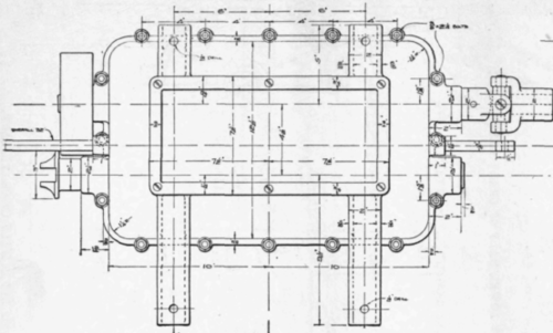
Fig. 16
Plan And End Views Of Complete Change Gear Case
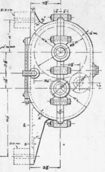
Fig. 17
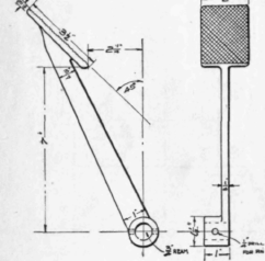
Fig. 23. Detail Of Clutch Release Pedal
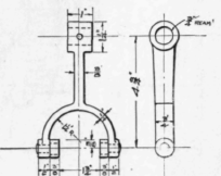
Fig. 24. Dltail Of Clutch Forked Lever
Fig. 18 shows the construction of the rear axle and the bevel gear drive. The revolving portions of the axle are of 1 7/8 in. solid steel turned down to 1 inch at the hubs and keyed in. The differential gear is of standard construction and is, therefore, not detailed. The hubs may conveniently be of phosphor-bronze or steel. The gear case is intended to be cast of aluminum alloy containing 25 per cent zinc. The same is used for the engine crank case and the change gear case. The revolving portions of the axle are enclosed in a 1 3/4 in. steel tube which is fitted with phosphor bronze bushings at its extremities. It will benoted in this connection that only plain bearings are used all through the construction of the car. Fig. 19 is a detail of the spring clip fitting for the rear axle. This consists of a steel casting which is bored to fit the axle tube and is clamped thereto and to the spring by means of a paiv of 3/8 in. "U" bolts.
Fig. 20 shows the construction of the front axle and hubs. The axle consists of a length of 1 1/2 in. tube brazed into the forked steering ends. The front hubs are the same as the rear ones with the exception, of course, that they are bored a running fit for he axle instead of being keyed on. Further details of the axle ends can be obtained from Fig. 2. Fig. 21 shows the reach fitting for the front axle. This is bored to fit the front axle tube and the reach is intended to be a turning fit for the lower portion so that the running gear may adjust itself to any unevenness of the road. The reaches consist of a pair of steel tubes, the location and length of which may be seen in Fig. 1. They have solid ends brazed in and a nut placed on the outside.
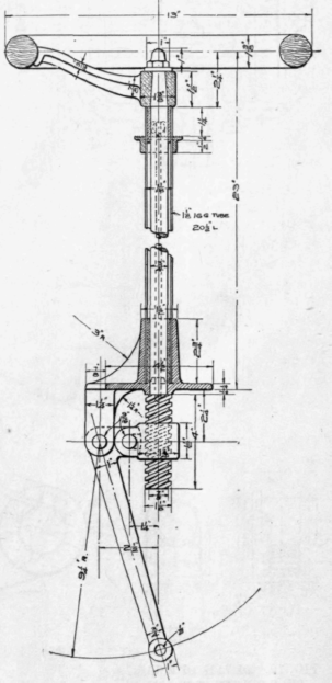
Fig. 22. Detail Of Steering Column
Fig. 22 shows the construction of the steering column. The tubular portion is stationary and has attached to it near the top the spark and throttle levers; the centre rod turns with the hand wheel and operates the screw at the bottom. The 6crew is 1 1/8 in. outside diameter and has three threads with a pitch of one thread per inch. The proportions of the linkage are such that about one and one-half revolutions of the hand wheel are required to turn the front wheels from one extreme to the other.
Figs 22 and 24 show respectively clutch, release pedal and the forked lever for disengaging the clutch. The latter has a pair of small rollers on the forked ends, which engage the grooved collar on the clutch shaft for drawing the cones apart. Fig. 28 shows the brake pedal. This, as well as the clutch pedal, should preferably be a steel forging. Fig. 20 shows the brake shoe, which may be a casting of alzinc and is faced with leather for friction surface. This may be secured to the metal surface of the shoe by means of shellac and a considerable number of wooden shoe pegs. The wear on this facing will probably be rapid but it can be easily and cheaply renewed.
Continue to:


My Books

