


Pipes
Description
This section is from the book "A Practical Workshop Companion For Tin, Sheet Iron, And Copper Plate Workers", by Leroy J. Blinn. Also available from Amazon: A Practical Workshop Companion For Tin, Sheet Iron, And Copper Plate Workers.
Pipes
To Describe A T Pipe At Right Angles
Let ABCD, fig. 47, be the length and diameter of the T; describe the semi-circle CED; divide the semicircle into any number of equal parts; from the points draw lines parallel to AC, as
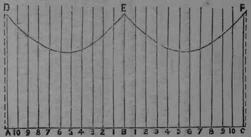
1, 2, 3, etc.; then set off the line ABC, fig. 48, equal in length to the circumference of the Pipe AB; erect the lines AD, BE and CF; set off on each side of BE the same number of equal distances, as in the semi-circle CED; from the points draw lines parallel to BE, as 11, 22, 33, etc.; make AD, BE and CF equal to AC; also, each of the parallel lines, bearing the same numbers as
11, 22, 33, etc.; then a line traced through the points will form the pattern required.
Fig. 47. Edges to be allowed for folding or riveting.
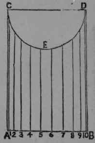
Fig. 48.
Pipes
To Describe A Pattern For A T Pipe At Any Angle
Draw the line AE, fig. 49; erect the line AB, the angle required; also, the line ED parallel to AB; make BD equal to the diameter of the Pipe; describe the semicircle BCD; draw the line FG parallel to BD; divide the semicircle into any number of equal parts from the points; draw lines parallel to AB, as 1, 2, 3, etc.
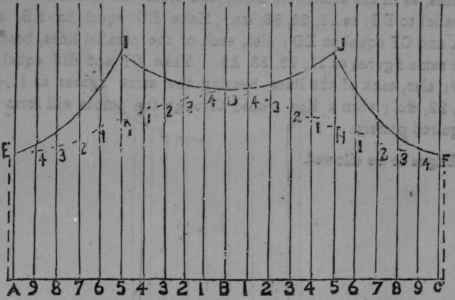
Set off the line ABC, fig. 50, equal in length to the circumference of the Pipe; erect the lines AE, BD and CF at right angles to AC; set off on each side of BD the same number of equal distances, as in the semicircle BCD, and from the points draw lines parallel to BD, as 11, 22, 38, etc. Make BD equal to AB, and EA and CF equal to ED; also, each of the parallel lines, bearing the same figures as 11, 22, 33, etc. Make GI and HJ equal to GD; also, each of the lines bearing the same figures as 11, 11, 22, 22, etc.; then a line traced through the points will form the required pattern.
Fig. 49. Edges to be allowed.
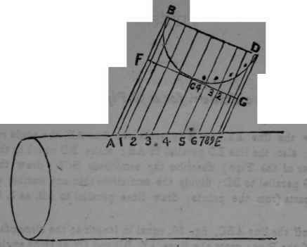
Fig. 50.
Pipes
Fig. 51. To describe a Pattern for a T Pipe, the Collar to be Smaller than the Main Pipe.
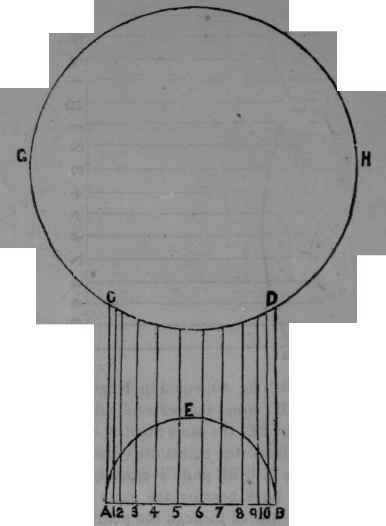
Let the circle OH, fig. 51, equal the large pipe, AB, CD, the Branch or Collar; describe the semicircle AEB; divide the semicircle into any number of equal parts; from the points, draw lines parallel to AC, as 1, 2, 3, etc.
Fig. 52.
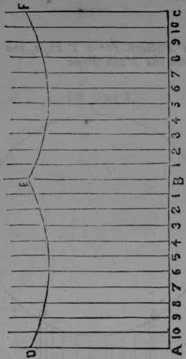
Set off the line ABC, fig. 52, equal in length to the circumference of the Collar AB; erect the perpendicular lines AD, BE and CF; set off on each of BE, the same number of equal distances as in the semicircle; from the points draw lines parallel to BE, as 1, 1, 2, 2, etc.; make AD, BE and CF equal to AC and BD; also, each of the parallel lines bearing the same figures as 1, 1, 2, 2, 3, 3, etc., then a line traced through the points will form the pattern.
Edges to be allowed.
Pipes.
Fig. 53. To describe a Pattern for a T Pipe at any angle, the Collar to be Smaller than the Main Pipe.
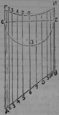
Let CE, fig. 53, be the diameter of the collar, and AB the angle required; describe the semicircle CDE; make CF and EH of equal length, with a radii equal to one-half the diameter of the large pipe; describe the arc FH; divide the semicircle into any number of equal parts; from the points draw lines parallel to AC, as 1, 2, etc. There must be an odd number of lines, as in the diagram, so that one of the lines run through the centre of the semicircle.
Fig. 54.
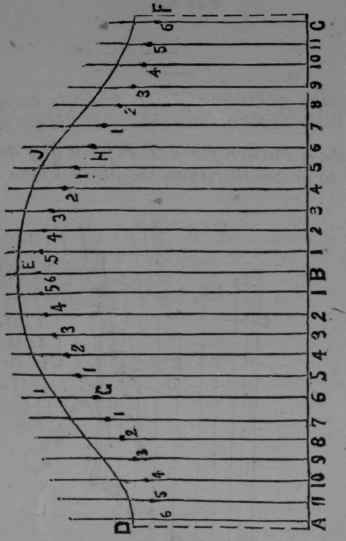
Set off the line ABC, fig. 54, equal in length to the circumference of the collar, CE; erect the lines AD, BE and CF; set off on each side of BE the same number of equal distances, as in the semicircle, and from the points draw lines parallel to BE, as 11, 22, etc.; make BE equal to AC in fig. 53; make AD and CF equal to BE; also, each of the parallel lines bearing the same figures; make GI and HJ equal to CF; also, each of the parallel lines bearing the same figures as 11, 11, 22, 22, etc.
A line traced through the last points will form the pattern,
Edges to be allowed.
Pipes.
Fig. 55. To describe a Pattern for a T Pipe at any angle, the Collar to set on one side of the Main Pipe.
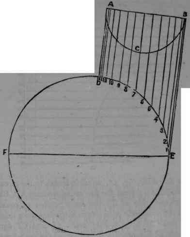
Let the circle FE, fig. 65, equal large pipe or boiler; make AB equal to the diameter of the collar or branch pipe, BE the angle required; describe the semicircle ACB; divide the semi-oircle into any number of equal parts; from the points draw lines parallel to BE, as 1, 2, 3, etc.
Fig. 56.
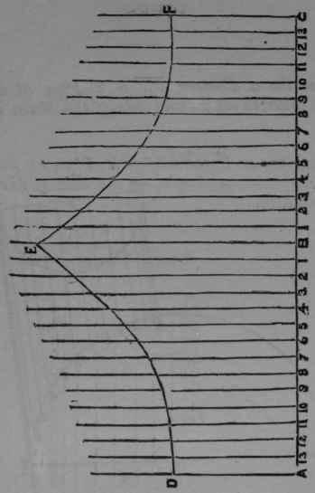
Set off the line ABO, fig. 66, equal in length to the circumference of the collar AB; erect the perpendicular lines AD, BE and CH; set off on each side of BE the same number of equal distances, as in the semicircle ACB; from the points draw lines parallel to BE; make BE equal to EB; make AD and CF equal to DA; also, each of the parallel lines bearing the same figures as 11, 22, 83, etc.; then a line traced through the points will form the pattern.
Edges to be allowed.
Pipes.
Fig. 57. To describe a Pattern for a Pipe to ft a Flat Surface at any Angle, as the side of the Roof of a Building.
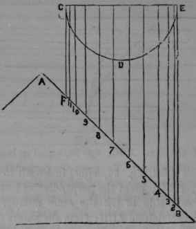
Let AB, fig. 57, equal the angle of the roof of a building; let CE, FB equal the pipe; draw the line CE; describe the semicircle CDE; divide the semicircle into any number of equal parts; from the points draw lines parallel to EB, as 2, 3, 4, etc.
Fig. 68.
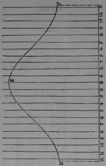
Then set off the line ABC, fig. 58, equal in length to the circumference of the cylinder CE; erect the perpendicular lines AD, BE and CF; set off on each side of BE the same number of equal distances, as in the semicircle CDE; from the points draw lines parallel to BE; make BE equal to BE; make AD and CF equal to FC; also, each of the parallel lines bearing the same number as 22, 33, 44, etc.; then a line traced through the points will form the pattern.
Edges to be allowed.
Pipes.
Fig. 59. To describe a Pattern for a Pipe to fit two Flat Surfaces, as the Roof of a Building.
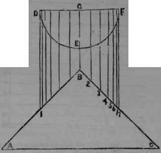
Let ABC, fig. 59, equal the pitch of a roof; let DF, IH, be the pipe; draw the line BG parallel to HF; draw the line DF at right angle to HF; describe the semicircle DEF; divide one-half the semicircle into any number of equal parts; from the points draw lines parallel to FH, as 2, 3, 4, etc.
Fig. 60.
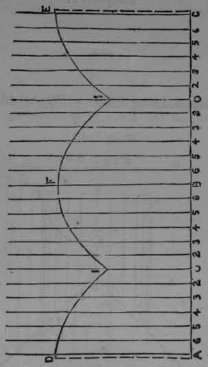
Set off the line ABC, fig. 60, equal in length to the circumference of the pipe DF; divide the line ABC into four equal parts, and erect the lines AD, OI, BF, OI, CE; set off on each side of OI, OI, the same number of equal distances as in one-half the semicircle; from the points draw lines parallel to BF; make AD, BF and CE equal to HF; make OI, OI equal to BG; also, each of the parallel lines bearing the same figures as 22, 22, 33, 33, etc.; then a line traced through the points will form the pattern.
Edges to be allowed.
Continue to:


My Books

