


On The Practical Design Of Columns And Struts. Part 11
Description
This section is from the book "Notes On Construction In Mild Steel", by Henry Fidler. Also available from Amazon: Notes On Construction In Mild Steel.
On The Practical Design Of Columns And Struts. Part 11
A further comparison may be made of the sections above described which is not without importance, and that is the extent to which the surfaces of the respective sections can be protected from the effects of corrosion, or, in other words, the extent to which the sections can be got at by the paint brush.
All the simple sections are fairly accessible, Figs. 151, 157, 160, having latticing on one or both sides, can be painted internally, while Figs. 163, 164, 169, 170, with solid plate flanges, have closed cells, which cannot easily be painted under ordinary conditions. Such closed cells are not infrequently filled with concrete, although the extent to which this acts as a preservative coating depends largely on the degree of close contact with the metal obtainable.
Figs. 155, 156, 159, 161, 162, and 165 to 168 can be readily painted inside and out. Figs. 152, 157, 158, 160, 163, 169, 170 will be either closed cells or accessible to the paint brush, if they have solid plate flanges or latticing respectively.
A temptation, often present to the mind of the designer when preparing his working drawing for a column or strut, prompts him to save time and trouble by only detailing, say, the cap and base to some convenient scale, and breaking off the remainder so as not to show to a true scale the entire height and length of the column or strut. This is a practice not to be commended, and one which the junior draughtsman is cautioned against, inasmuch as the opportunity is lost of viewing the true proportions of diameter or least dimension to height, a factor which is always of great importance.
The complete elevation in true scale enables the trained eye of an experienced designer to verify the theoretical conclusions he may have arrived at as to the proportions of his column, and may save him the embarrassment of the after-contemplation of a work which may either look dangerously slender or unnecessarily stout.
The above remark is perhaps the more necessary, inasmuch as in the following details of columns which are now presented, owing to the exigencies of illustration, the details of the column will be given rather than the complete elevation.
The examples which follow are taken from the working drawings of columns actually constructed.
Fig. 176 is the side elevation of a riveted steel column of the type shown in Fig. 162, for supporting a heavy warehouse floor with roof over, the building consisting of ground and first floor only.
The section consists of four angles, four flange plates, and one solid web. In order to distribute the heavy concentrated load properly over the concrete bed on which it stands, a cast-iron base plate is employed, shown in side elevation in Fig. 177, in end elevation in Fig. 178, and in plan in Fig. 176.
The meeting surfaces of the base plate and column would in such a case be machined carefully square to the vertical axis of the column, and the bed-plate fixed carefully level, and the concrete surface grouted up, or prepared with sheet lead or felt.
In Figs. 181 and 182 we have shown the upper portion of a similar type of column of somewhat lighter section, showing the details of the cap.
The connection of the cap of the column shown in Fig. 177, with the floor girders and the base of the column above, is an illustration of one method of dealing with a question which will constantly present itself to the mind of the designer, viz. whether the column should give way to the connections at each floor, or vice versa, or, in other words, whether the columns should be in one continuous length from top to bottom, or broken wherever attachments for floor girders have to be made. In the writer's view no hard-and-fast rule can be laid down. Where the column spacing is wide, and the floor girders, as in the case under consideration, are of considerable span, carrying heavy loads, it appeared desirable that the detail of girder seating should occupy the first place, especially when the column next above, carrying the roof load only, is of moderate scantling and the load light.
Fig. 176. Scale ½ inch = 1 foot.
Fig. 177. Scale ½ inch = 1 foot.
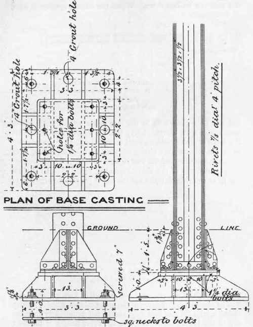
Fig. 178. Scale ½ inch = 1 foot.

Fig. 179. Scale 1 inch = 1 foot.
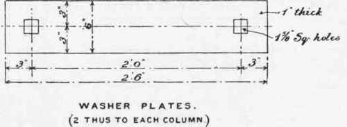
Fig. 180. Scale 1 inch = 1 foot.
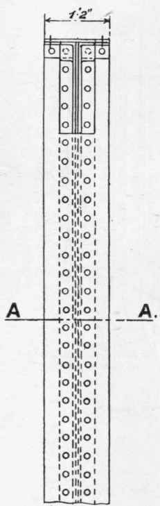
Fig. 181. Scale ½ inch = 1 foot.
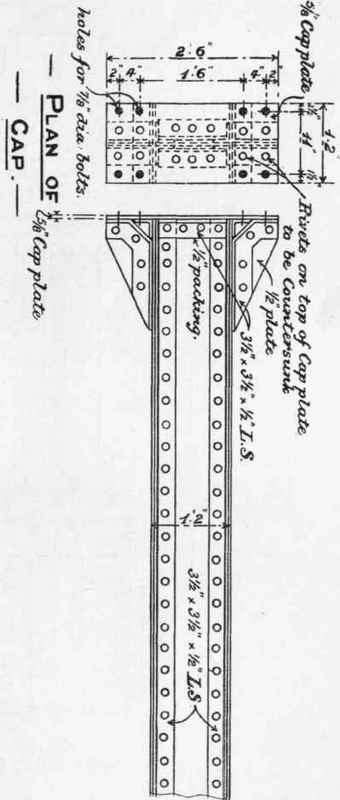
Fig. 182. Scale ½ inch = 1 foot.
In pursuance of the above reasoning, Figs. 183 and 184 show the front and side elevations of the cap of the column arranged to take the ends of the principal and secondary floor girders, and it will be observed that the base of the upper column, which, as above stated, carries the roof load only, stands, not immediately upon the cap of the lower column, but upon the upper flanges of the floor girders, the compressive stresses being brought down to the lower column by means of the webs of the girders, which are shown in detail in sectional plan in Fig. 185, and which are strengthened by-additional plates and angles to enable them to do this duty. The base of the column above is shown in sectional plan in Fig. 186, on the line HH (Figs. 183 and 184).
These figures then illustrate a case where the continuity of the column structure has been broken in order to meet girder requirements. But it must not be supposed that this is an example to be followed where the conditions are not similar.
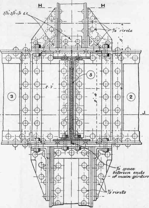
Fig. 183. Scale 1 inch = 1 foot.
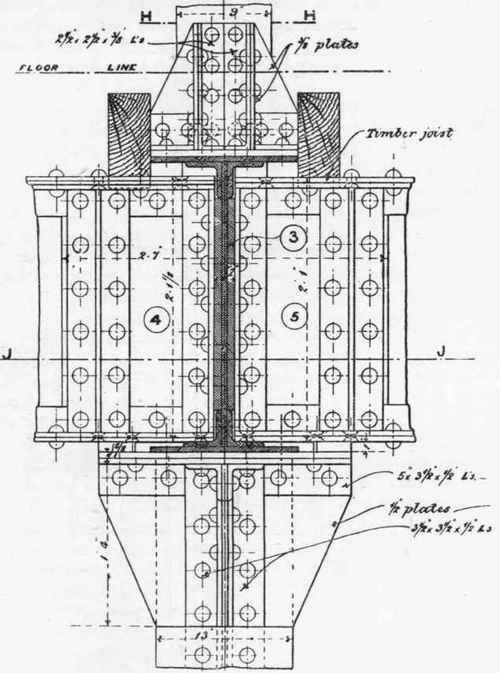
Fig. 184. Scale 1 inch = 1 foot.
Fig. 186.
Scale 1 inch = 1 foot.

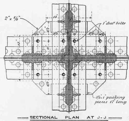
Fig. 185. Scale 1 inch = 1 foot.
Continue to:


My Books

