


Fire Escape. Part 3
Description
This section is from the book "The Engineer's And Mechanic's Encyclopaedia", by Luke Hebert. Also available from Amazon: Engineer's And Mechanic's Encyclopaedia.
Fire Escape. Part 3
The bullet and cord are thrown over the house by the cross-bow; to this cord a stronger one. is attached, and drawn over the house by the former, and so on, until a chain ladder or escape is eventually elevated. To act upon this plan, however, with any good chance of success, requires the men to be regularly trained for the purpose, as they are in Edinburgh, where they are exceedingly skilful in the management of all their fire machinery.
Mr. Buston introduced a fire escape, consisting of a large strong canvass sheet, with loops all round to hold on by; this being held under the window at which any person is situated, by eight or ten persons, the party above leaps out of the window into the middle of the sheet, which catches him uninjured. Although this is by no means the most pleasant mode of escape, nevertheless numberless experiments have proved it to be a safe and effectual one. As this escape takes up but little room, and is ready for use in a few seconds, it is well adapted to be carried by the fire engines, and most of those in London are now provided with one of this kind.
Having thus briefly noticed the most celebrated fire escapes of a portable nature, we proceed to describe those of a larger kind; and first of carriage ladders. In the year 1809 Mr. John Davies submitted to the Society of Arts a fire escape, which consisted of three ladders connected to, and sliding upon, each other, by means of ropes worked by a small windlass; a second windlass raised and lowered a cradle, supported by ropes passing over pulleys at the top of the uppermost ladder. This machine was mounted upon a low four-wheeled truck, drawn by a horse or by six men. Subsequently, Mr. Gregory greatly improved upon this escape; he employed three ladders sliding on each other, which, when lowered, were balanced horizontally upon a convenient frame mounted on a light four-wheeled carriage. When in this position they are capable of being run under low gateways, etc. with great facility. The ladders are brought into the perpendicular position, and then raised by a small windlass in the front of the machine, to any required height between ten feet and forty; the ladders are then inclined towards the window, upon the sill of which the top may be made to rest.
To obtain a greater elevation than forty feet, one or more joints can be carried up and affixed, in the manner already described under the head of Portable Ladders. A cradle accompanies this machine, for the assistance of those who cannot descend the ladders. Mr. Gregory's ladder escape has been but partially employed for that purpose; as a valuable and convenient ladder, however, it has been very extensively used by architects and others.
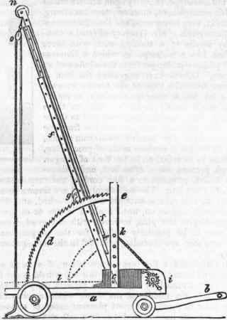
Mr, John Hudson, the founder of a short-lived society for preventing loss of life by fire, in 1829, constructed an escape-ladder, differing in some respects from that of Mr. Gregory, although upon a similar principle. The following is a side view of Mr. Hudson's apparatus; a is the carriage mounted on four wheels, the front pair of which turn with their axis and handle b under the carriage, for the facility of guiding, stowage, etc.; f f are three ladders sliding in grooves one within another. The foot of the lowest ladder is hinged to a revolving centre in the middle of the floor of the carriage; d is an arched frame forming the quadrant of a circle, with ratchet-teeth on its edges, in which drops a pall or click g on a cross bar fixed to the back of the lowest ladder. The ladders usually lie in a horizontal position, as shown by the dotted line f; the palls and ratchet-teeth prevent the ladders from falling back while being elevated. In order to place them in the oblique position for use, they may be elevated by hand, or more easily by turning the windlass i round the barrel of which the rope k is wound, and the other end of it fastened to the ladders at about three feet above the floor.
The ladders being thus brought to the position represented in the engraving, the motion of the windlass is continued, which winds off the rope from the ladders, and elevates them successively one above the other, until they attain the greatest height. The rope k passes through a pulley near the bottom of the lowest ladder, then over the top of it to the bottom of the next, and then over the top of the same to the bottom of the uppermost ladder. The pivot to which the ladders are hinged, is for enabling them to be veered round when it would be inconvenient to turn the earriage. The horizontal position is given to the ladders for enabling the machine to be conveyed through low passages, etc. There is a roller n at the top of the ladder, to prevent friction when moving up against a wall, and a tackle fall at o for cradles, etc.
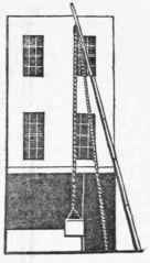
Mr. Joseph, who entertained a strong objection to the use of a connected series of ladders, submitted the following novel contrivance to public inspection: - a is a carriage capable of being drawn by two men, on which is fixed an elevated part b, sustaining a column of wood c; within this there is a smaller column of iron, capable of being raised by a rack and pinion, acted upon by the winch d; on the top of this internal column is an iron arm e on a swivel, having a cleft at its extremity to receive the long bar or lever f fastened to it by a bolt. The lower end of this bar is secured to the carriage by a pulley-tackle, which admits of an easy and secure adjustment at pleasure; to the upper end of this bar is suspended the cradle, etc. in the usual manner, with guy ropes to guide the cradle in its descent ,* k is the handle for drawing the carriage. There is a small rope ladder at f, and a bolt and chain at the top of the column, for fixing the internal pillar (which has a range of eight feet) at the required elevation. The pillar has a joint near its base, by which it is turned down into the horizontal position whenever it is required to pass under gateways, etc.
Continue to:


My Books

