


Diagrams For Preliminary Estimates Of Quantities
Description
This section is from the "Construction Of Masonry Dams" book, by Chester W. Smith. Also see Amazon: Construction Of Masonry Dams.
Diagrams For Preliminary Estimates Of Quantities
For a preliminary estimate of the quantities involved, based upon profiles of earth and rock surfaces across the valley, use accompanying diagrams as follows:
For masonry in a dam without overflow, assume as acceptable, Wegmann's Practical Profile No. 2 as modified on page 616 of the American Civil Engineers Pocket Book. (See section "A" Fig. 40.) For cu. yd. of masonry per lin. ft. of dam read curve "A" for neat section to a horizontal base not including masonry in cutoff trench.
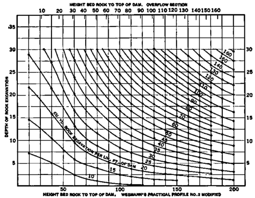
Fig. 41. Diagram showing cu. yd. of rock excavation.
If the dam is built on surface of rock add for masonry in cut-off trench as per curve "C".
If rock is excavated and masonry slopes can start from the original rock surface, as at "E," read curve "A" for a height above rock surface, and add an amount equal to rock excavation as obtained from diagram Fig. 41.
If masonry slopes must be extended down to a certain elevation below original rock surface, as at "F," read curve "A" for a height of dam above that elevation, and add an amount equal to the rock excavation below that elevation.
For masonry in an overflow darn, proceed precisely as above, reading curve "B" Fig. 40. Then if on account of height of dam, or for another reason, an apron is necessary, add an amount obtained from curve "D".
For rock excavation, read diagram Fig. 41 in which ordinates equal depth of rock which it is assumed necessary to excavate; abscissa represent width of excavation in terms of height of dam, which height should be considered as starting from the elevation where the neat masonry slopes begin. Curves show cu. yd. per lin. ft. and include cut-off trench as per curve "C" Fig. 40. If applied to an overflow dam with an apron, add to rock excavation as thus determined an amount at least equal to curve "D" Fig. 40, masonry in apron.
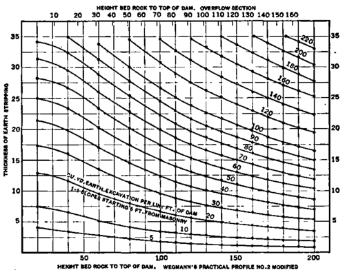
Fig. 42. Diagram showing cu. yd. of earth excavation.
For Earth Excavation
Read diagram Fig. 42 similar to rock excavation diagram, observing same rule for height of dam. Curves show cu. yd. per lin. ft. of dam for excavation to 1-1 slopes starting 5 ft. from neat lines of masonry. If applied to an overflow dam with an apron add for tentative estimate 1 cu. yd. per ft. depth of stripping. On both excavation diagrams are two scales for height of dam, according to which masonry section is being considered.
List Of Items In An Estimate
Although most of the various elements of cost have been discussed, as well as the various alternate modes of procedure for different conditions, the outline of an estimate will be here presented. Even at the expense of some repetition it will be as well to assemble the different items or possible items. Obviously no one estimate will include all of the items as many are mutually exclusive; some consideration, probably in most cases very brief, will eliminate many of them. Certain methods and items may be tentatively adopted subject to change on more complete or accurate information. According to the stage of the project, the purpose of the estimate, the accuracy of the surveys and information, the time and money available and the particular experience and judgment of the estimator; these items may be roughly estimated in total, or they may be analyzed, subdivided and figured to any required degree of accuracy.
A Plant;
C Material entering into work;
D Labor;
E General expenses; F Contingencies; G Overhead expenses; H Profit.
A. Plant
Total plant charge may be considered under the following heads:
(1) First cost of plant at point of purchase.
(2) Freight on plant to railroad station nearest work; requiring that weights be approximately known and freight rates looked up.
(3) Haul from railroad station to dam site.
(4) Erection, including cost of materials (as cement and lumber) entering into the various housings and settings. Labor and materials of maintenance will be taken up elsewhere.
(5) Cost of haul back to railroad at end of work.
(6) Cost of freight to some point where plant can be sold or used on other work.
(7) Salvage value, a credit item; i.e., the sum of items Nos. 1 to 6 minus No. 7 gives the total plant charge. Item A-1. May be listed as:
Power
Motors
Tramways
Hoisting engines
Derricks
Pile drivers
Drills
Channelers
Stone-dressing machines
Pumps
Crushers
Grinding rolls
Mixers
Screens
Elevators
Bins
Locomotives
Cars
Track
Small tools
Conveyors Dump buckets Scows - boats
Machine
Carpenter
Blacksmith
Shops and equipment
Tanks
Steam shovels
Dredges
Rollers
Scrapers
Water carts
Carts
Wagons
Live stock
Camp and office buildings and equipment
Water supply
Sanitation
Stables
Lights.
Power should be further itemized depending on the source and manner of distribution:
For Steam Direct To Engines, One Or More Boiler Installations Comprising
(1) Boiler house
(2) Chimney
(3) Water supply
(4) Boilers
(5) Feed pump
(6) Feed-water heater
(7) Fuel storage and handling equipment
(8) Distribution piping
Continue to:


My Books

